FRAME Coordinate System and Calibration
Stage Coordinate System
Origin Position
The zero position of the XYZ stage corresponds to the A1 position of a standard multiwell plate. There is an offset between the virtual position displayed in ImSwitch and the actual physical position on the stage.
Calibration Target
A calibration sample is provided to help locate the central reference point at coordinates xy = 63.5/46 mm:
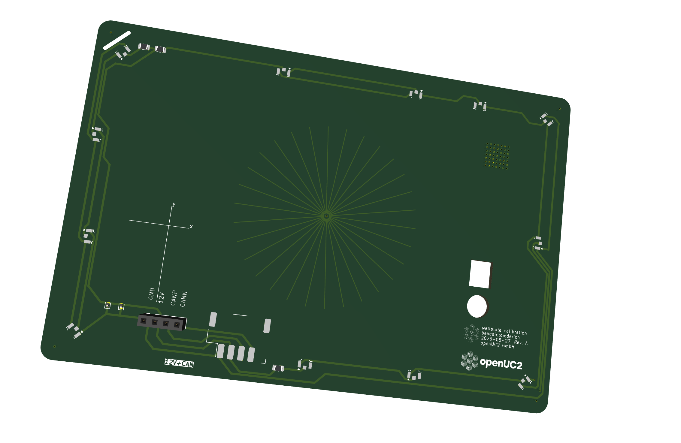
Calibration target with crosshair lines to help navigate to the center position
The calibration target features lines that help users navigate to the center position and can also be used with fluorescence illumination.
ToDo Armin 250804: Mehr erklärungen dazu? Was sehe ich hier und warum?
Stage Travel Range
The maximum travel range is 127 x 86 mm, suitable for multiwell plates:
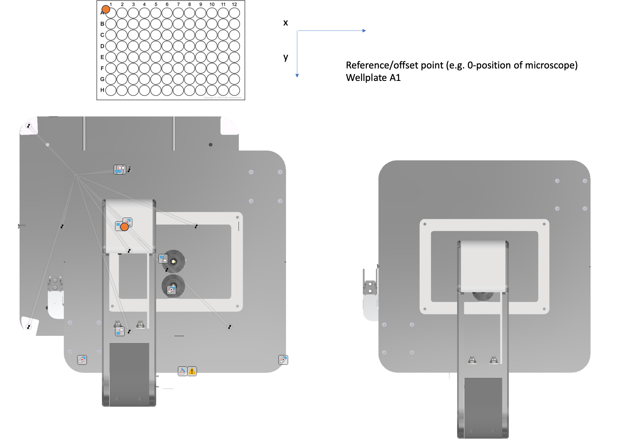
Stage coordinate system showing maximum travel range
ToDo Armin 250804: Das linke untere Bild ist für mich schwer verständlich und ergibt auch keinen Sinn (die Objektive sind verschoben zum Strahlengang/beleuchtung) Was soll die Aussage des Bildes sein?
Axis Directions
The coordinate system directions and orientations are defined as follows:
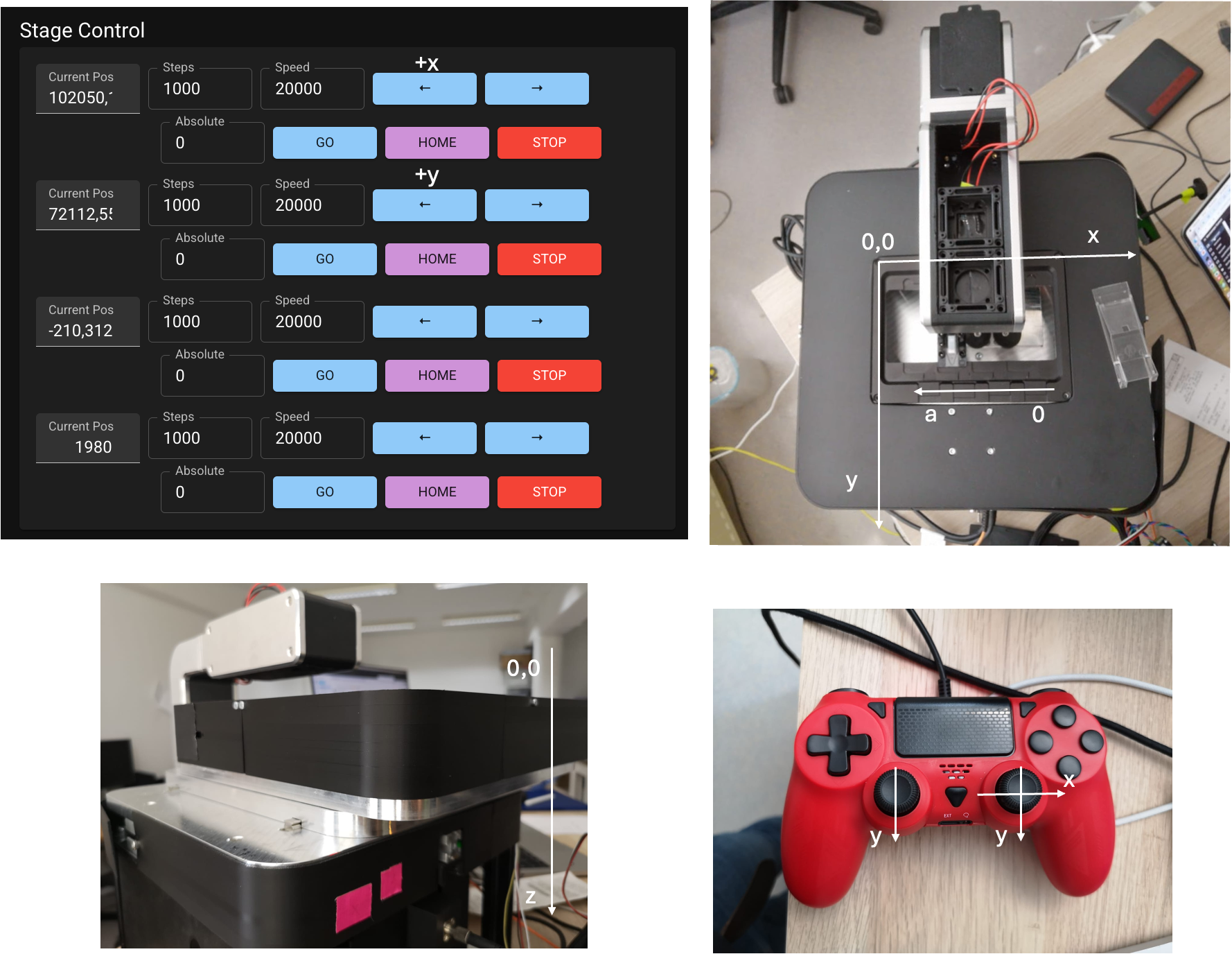
Detailed coordinate system showing axis directions and orientations
ToDo Armin 250804: Was sagt das a ... 0 im rechten oberen Bild aus? Auf dem Joystick ist zwei mal Y? Soll der rechte Button Z anstatt Y sein?
Calibration Procedures
Stage Position Calibration
- Load Calibration Target: Place the provided calibration sample on the stage
- Navigate to Center: Use the crosshair lines to navigate to position xy = 63.5/46 mm
- Record Offset: Note the difference between displayed and actual positions
- Update Configuration: Enter the offset values in the ImSwitch configuration
ToDo Armin 250804: Hier detaillierter beschreiben? Halte ich für notwendig, wenn der Kunde anhand dieser Anleitung in der Lage sein soll, eigenständig zu kalibrieren.
Optical Alignment
For detailed optical alignment procedures, see:
Technical Specifications
- Coordinate Origin: Multiwell plate position A1
- Calibration Point: 63.5/46 mm
- Maximum Travel: 127 x 86 mm
- Resolution: 0.3125 μm per step (configurable)
- Repeatability: ±2 μm (typical)
ToDo Armin 250804: Angaben nicht vollständig konsistent zu 03_Technical_Specifications.md. Z.B. Repeatbility unterschiedlich und auch Travel range.