FocusLock
IR laser focus-lock module
Our microscope platform includes an optional focus-lock module that can be added to the FRAME at any time. The goal is to keep the sample in focus automatically during long experiments (e.g. STORM acquisitions, time-lapse imaging, incubator workflows) and to enable fast “return to focus” moves when scanning many XY positions (e.g. well plates).
Principle of operation
The below simulation from Ray-Optics shows the core idea:
Infrared laser injection
- A collimated infrared (IR) laser beam is routed into the microscope and aligned into the back focal plane (BFP) of the objective.
- Injecting the beam into the BFP ensures the beam exits the objective at a defined angle and probes the sample plane in a repeatable way.
Reflection at the coverslip
- At the sample, a small fraction of the IR light is reflected (typically at the coverslip/sample interface).
- The reflected beam travels back through the objective.
Separation and detection
- A dichroic / beamsplitter designed for IR separates the returning beam from the illumination path and directs it onto a dedicated monochrome camera (the “focus camera”).
Focus signal from spot motion
- As the sample moves along Z (focus direction), the detected spot position shifts on the focus camera (typically along X).
- This provides a continuous measurement that can be used as a feedback signal.
Two operating modes
1) Continuous focus lock (feedback mode)
- The system continuously measures the IR spot position and converts it into a focus error signal.
- This is most useful for long recordings where drift is expected (thermal drift, incubator drift, mechanical relaxation).
2) One-shot focus correction (positioning mode)
- The system measures the current focus offset once and performs a single Z correction.
- Typical use: multi-position experiments (well plates / mosaics), where each XY position gets an automatic focus adjustment before imaging.
Video demonstration
The following video shows the focus-lock in action during a long time-lapse experiment with deliberate temperature changes. The focus-lock keeps the sample in focus despite significant drift.
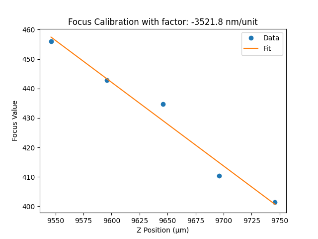
Calibration: spot position → defocus in µm
To convert “spot position” into an actual defocus value (µm), we run a short calibration:
- The system performs a controlled Z sweep over a defined range.
- For each Z position, the software measures the spot position on the focus camera.
- The result is a mapping curve (ideally close to linear over the working range).
- We fit a curve and accept the calibration only if the fit quality (e.g. R²) exceeds a threshold.
- Once calibrated, the focus-lock can report defocus in micrometer steps and apply accurate Z corrections.
Practical considerations and tuning
A few parameters strongly affect robustness:
- Camera exposure time: must be long enough for a clean signal, short enough for responsive feedback.
- Camera gain: should avoid saturation while keeping sufficient SNR for stable peak/spot detection.
- Peak/spot detection settings: tuned so the software reliably tracks the correct reflection spot.
The web interface exposes these settings and visualizes:
- Live focus camera images (optional polling)
- Continuous focus signal over time (time graph)
- One-shot correction triggers in the experiment view
Alignment and setup
For first-time setup or when switching objectives, the laser path may need adjustment.
- We provide a compact XY adjustment stage mechanically linked to the FRAME.
- This stage moves the focus-lock module in an intermediate plane so the IR beam is aligned to hit the objective’s BFP correctly.
- Best practice for calibration: use a reflective sample or a clean coverslip interface so the reflection spot is clear.
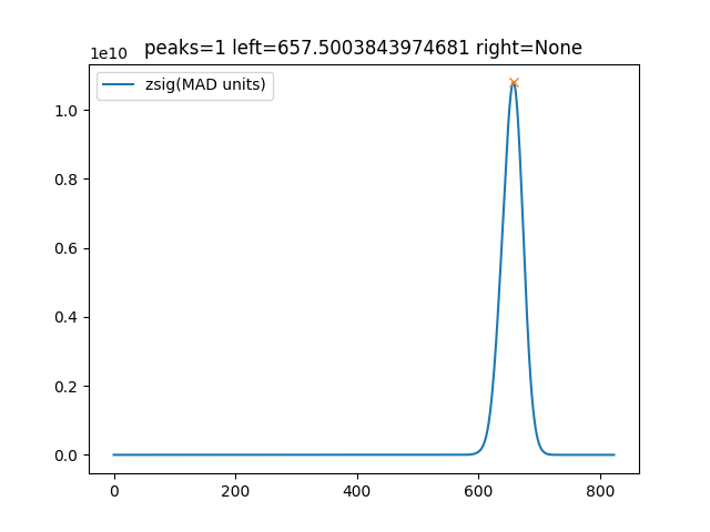
Two reflections (two spots)
Sometimes you may see two reflection spots, typically from the two coverslip surfaces.
- That’s normal.
- We aim to make the two spots well separated so the software can track the correct one reliably.
- Separation can often be improved by slightly shifting the module along the objective’s X direction (geometry dependent).
This image shows one distinct peak:
Hardware notes and roadmap
- Current implementation uses an IR laser (≈850 nm) and a monochrome camera integrated into the Raspberry Pi-based FRAME system.
- The focus camera is read automatically, and the focus value is computed in software.
- The module is designed to be compact and cost-effective, enabling advanced experiments even in constrained environments (e.g. incubators).
- We are currently in an extended testing phase before full release.
Long-term, we plan to offer different add-ons and variants optimized for different imaging channels and experimental needs.
Feedback welcome
This focus-lock module is actively evolving. If you test it in your workflows, we’d love to hear:
- which objectives you use
- the typical drift you see (per hour)
- your calibration quality and usable linear range
- edge cases (two spots, weak reflections, high background)