Installation and Setup
Pre-Installation Checklist
Before beginning installation, ensure you have:
- Read all safety information in Safety and Compliance
- Verified environmental conditions meet specifications in Technical Specifications
- Prepared adequate workspace (minimum 1 m × 1.5 m)
- Organized necessary tools (see Tool Requirements below)
- Verified power supply compatibility in Technical Specifications
Package Inspection
Upon Delivery:
- Inspect packaging for damage during shipment
- Document any visible damage with photographs
- Check that all packages are received according to packing list
Unpacking Procedure:
- Use proper lifting techniques (system weight: 25-35 kg)
- Remove packaging materials carefully to avoid damage
- Keep packaging materials until installation is complete
- Verify all components against the packing list
Standard Package Contents - Packing List
Main System Components
- FRAME main unit (frame and base assembly)
- XYZ positioning system
- Illumination arm incl. light source (2x1 cubes)
- Control electronics unit
- camera
- Power supply for FRAME
- USB/CAN interface cables
- Camera cable
- USB-A to USB-C Cable
- Emergency Stop
Optical Components
- Optical Module preconfigured (3x3x2 Cubes)
- Objectives as ordered
- Camera interface adapter
Laser Module
- separate Laser module (3x2x1 cubes)
- Laser safety cover
- separate Laser (if applicable)
- separate Power supply for Laser (if applicable)
- Separate key
Accessories
- Sample holders and clips
- Biological test specimen
- Calibration target
- Ruler Target
- PS4-Controller
- Tool kit
- Documentation package
- Software installation media/download links
Tool Requirements
Essential Tools
- Allen key set (2, 3, 4, 5, 6 mm)
- Phillips head screwdriver
- Flathead screwdriver
- Adjustable wrench
- Digital multimeter (for electrical verification)
Optional Tools
- Optical cleaning supplies
- Antistatic wrist strap
- Digital level
- Vibration measurement device
Unpacking
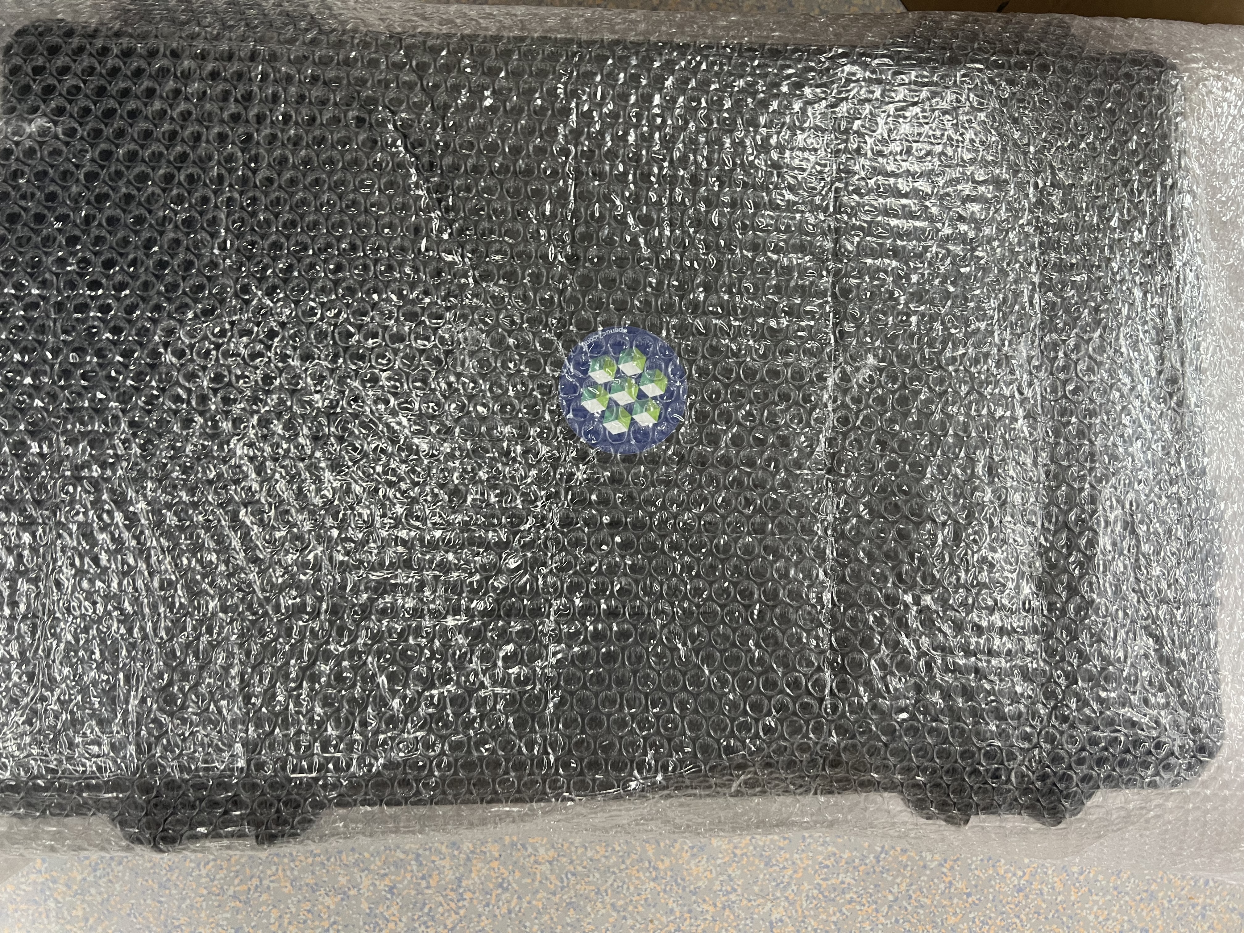 Take Case wrapped in bubble foil out of cardboard box.
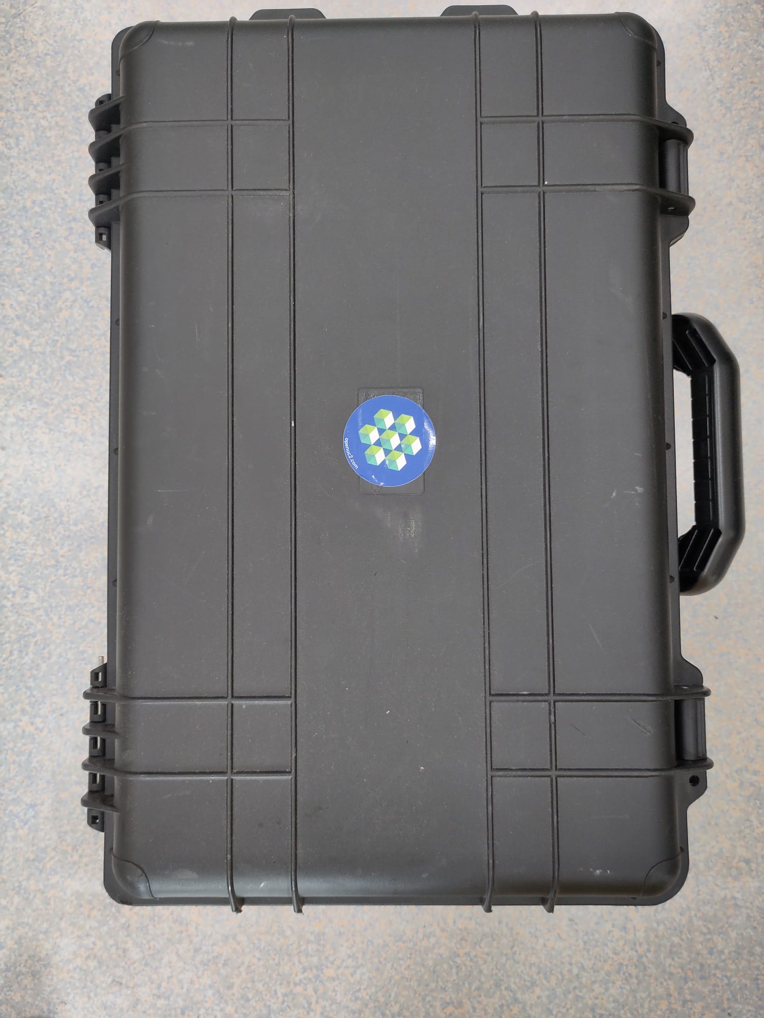 Case, that holds the FRAME inside, with bubble foil removed.
 Carefully open the case and ensure that there is no outer damage to the package. Store this case carefully and reuse it if necessary - it's a great suit case :)
![]()
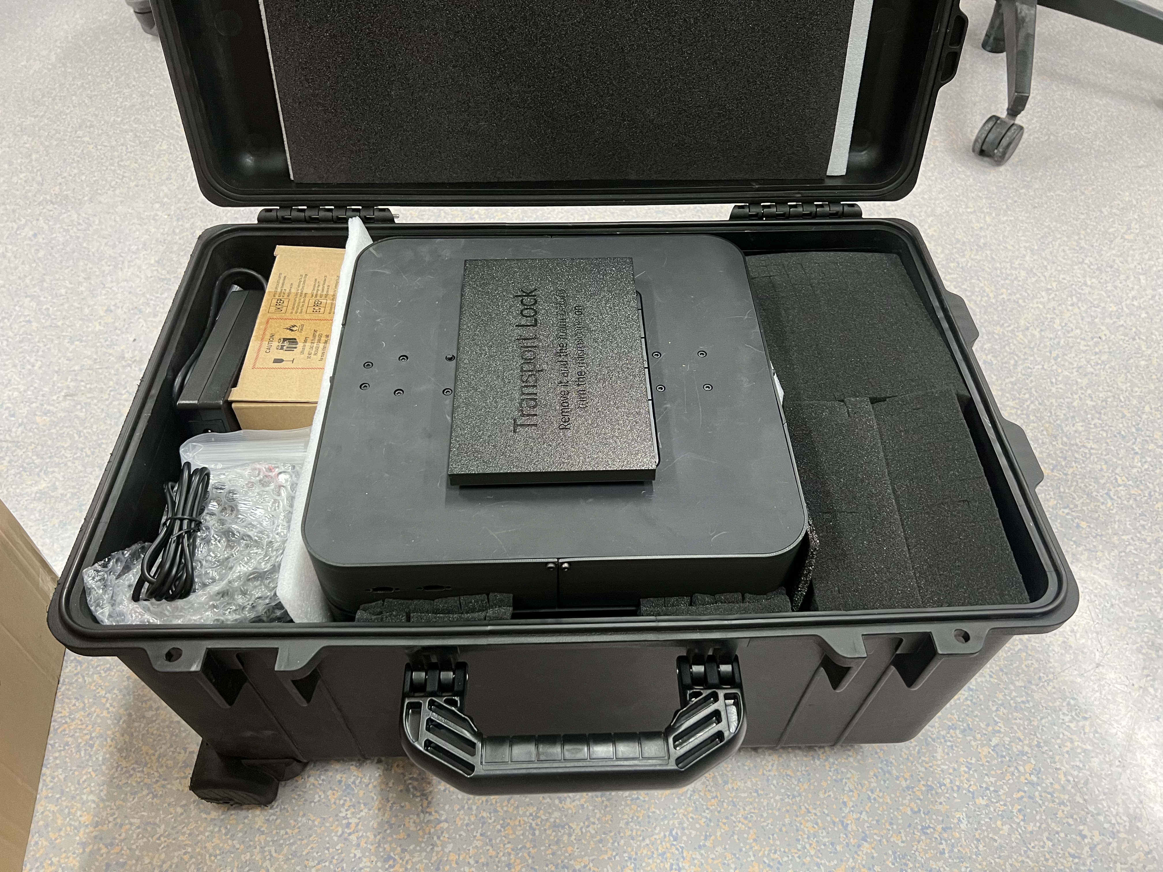
![]() Remove the Transport lock on top of the FRAME.
Remove the Transport lock on top of the FRAME.
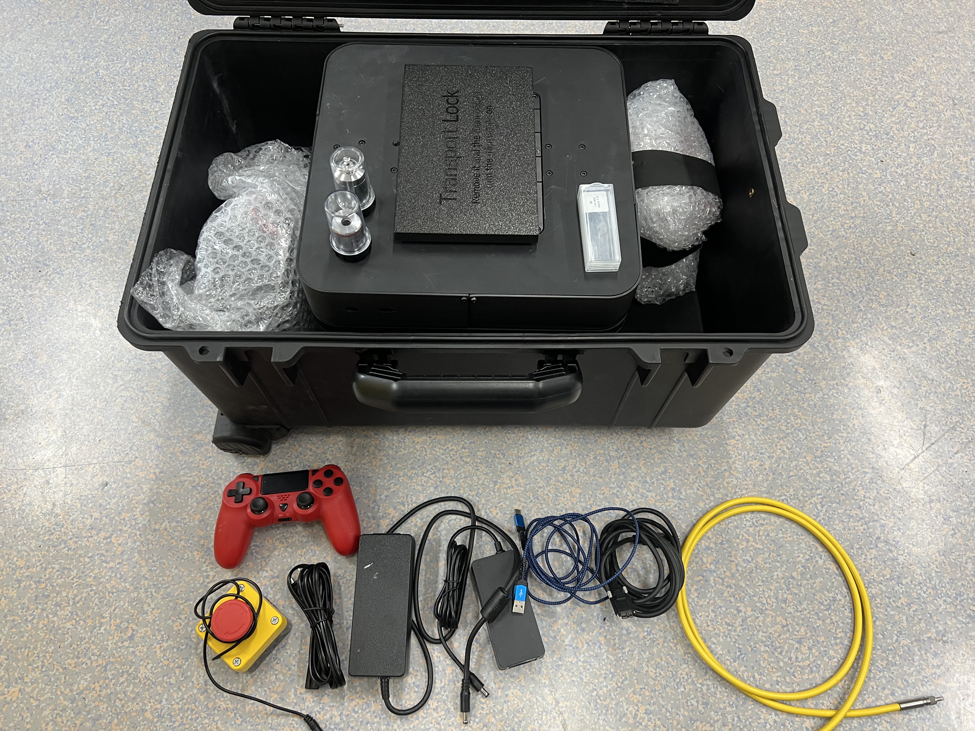 The FRAME is covered with packaging material, foam and bubble foil, unwrap the parts and take out the components, starting with the smaller parts, including the illumination arm. The FRAME body itself is very heavy, so please make sure you get additional support and move the box out of the suitcase carefully. Hold it from the lower end don't lift it holding the Z-stage!, put this on a surface that is decently stable!
![]() Don't forget to remove all foam parts inside the stage.
Don't forget to remove all foam parts inside the stage.
Frame Positioning and Setup
Initial Frame Positioning
Position Main Frame:
⚠️ CAUTION: Use proper lifting techniques. Two-person lift recommended.- Place frame on designated work surface
Level the System:
- Use bubble level or digital level
- Adjust position on surface until level in both X and Y directions
- Verify stability by gently pressing corners
- Re-check level after 30 minutes
Surface Requirements:
- Stable, level surface capable of supporting 50 kg
- Minimal vibration environment
- Place away from air conditioning vents and heat sources
- Good lighting for assembly work
Power Requirements:
- 230V AC, 50/60 Hz power outlet (or 115V with adapter)
- Dedicated circuit recommended
- Power outlet within 2 meters of installation location
- Proper grounding required
Environmental Conditions:
- Temperature: 15°C to 35°C
- Humidity: 30% to 80% RH, non-condensing
- Clean environment, minimal dust
Component Installation
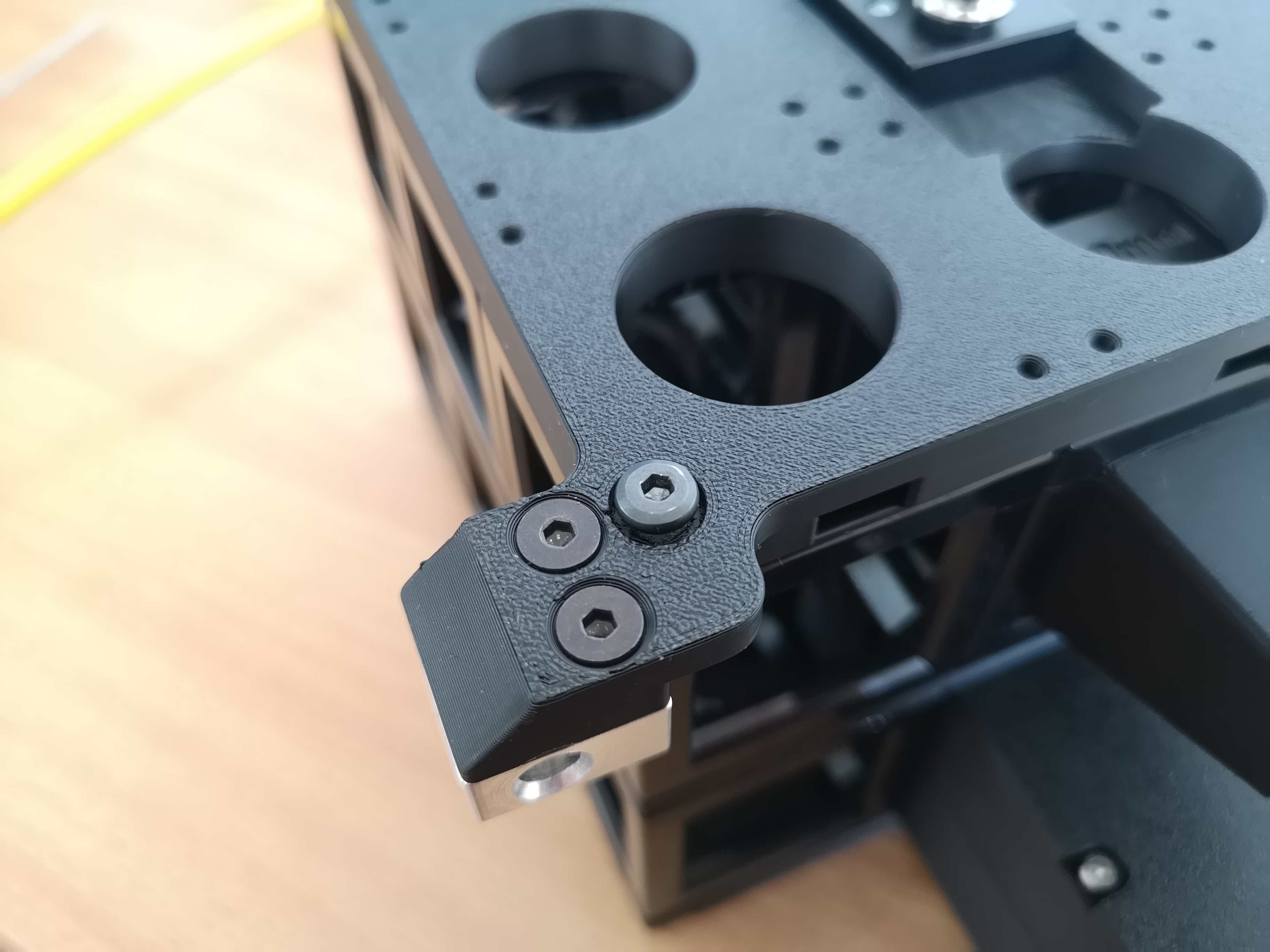
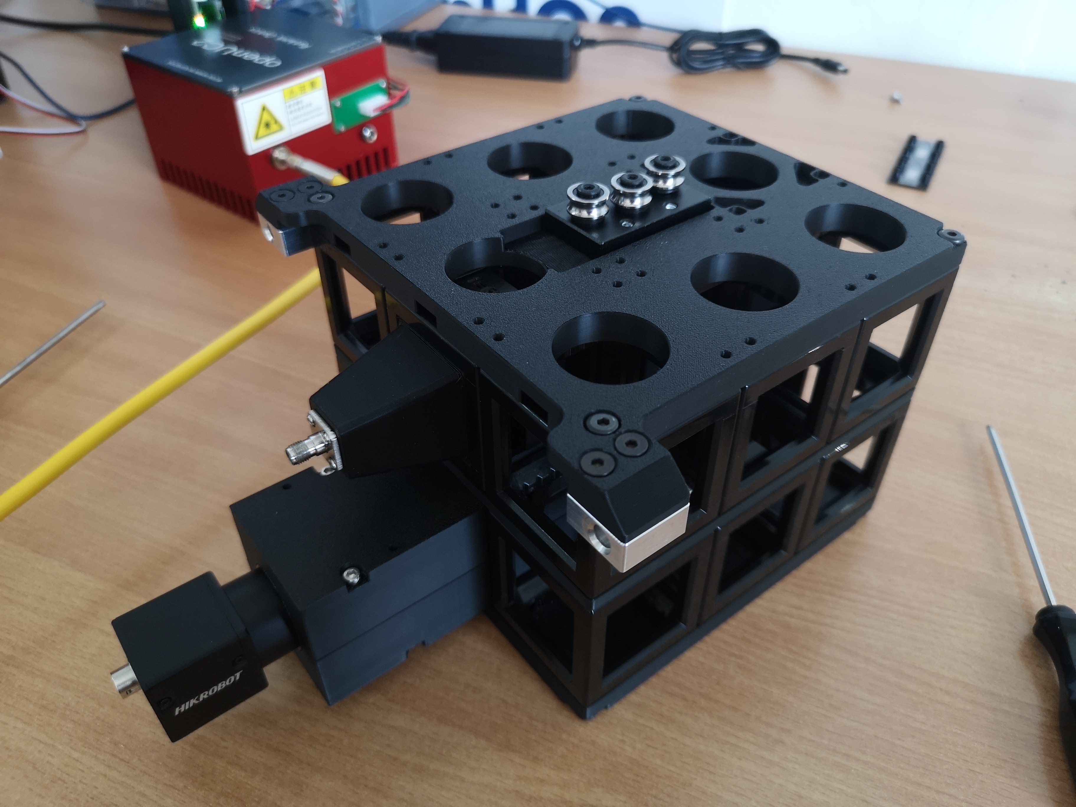
Mounting the Illumination Arm
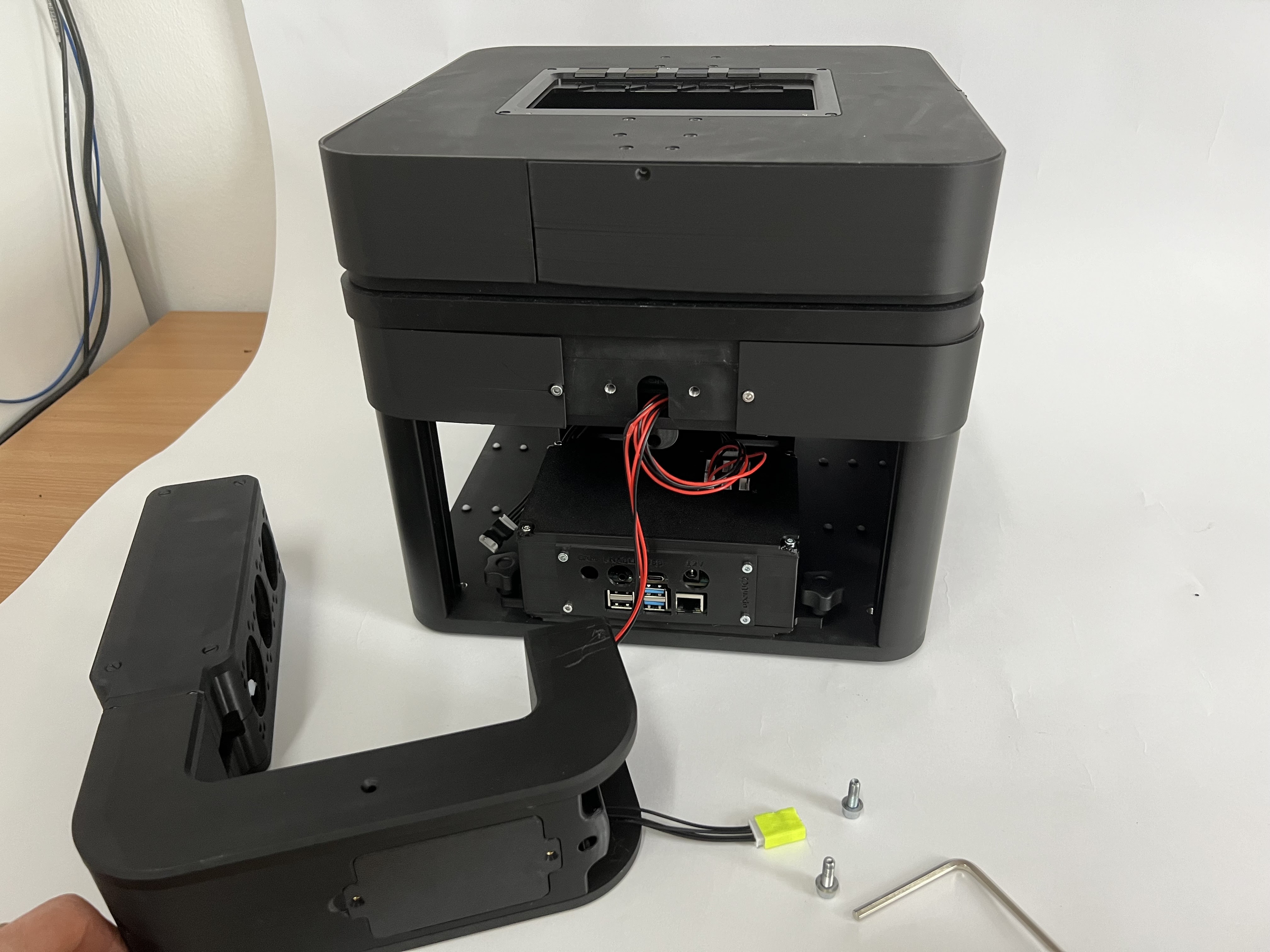 We start by mounting the illumination arm with the two M5 screws. For this get an appropriate 4mm allen key and secure the two screws that are sitting in the back of the frame and then attaching the illumination arm on the back. It's easiest if you have a second person holding the illumination arm and the second person is tighenting the screws. You can use a cube to have a spacer between the stage and illumination arm.
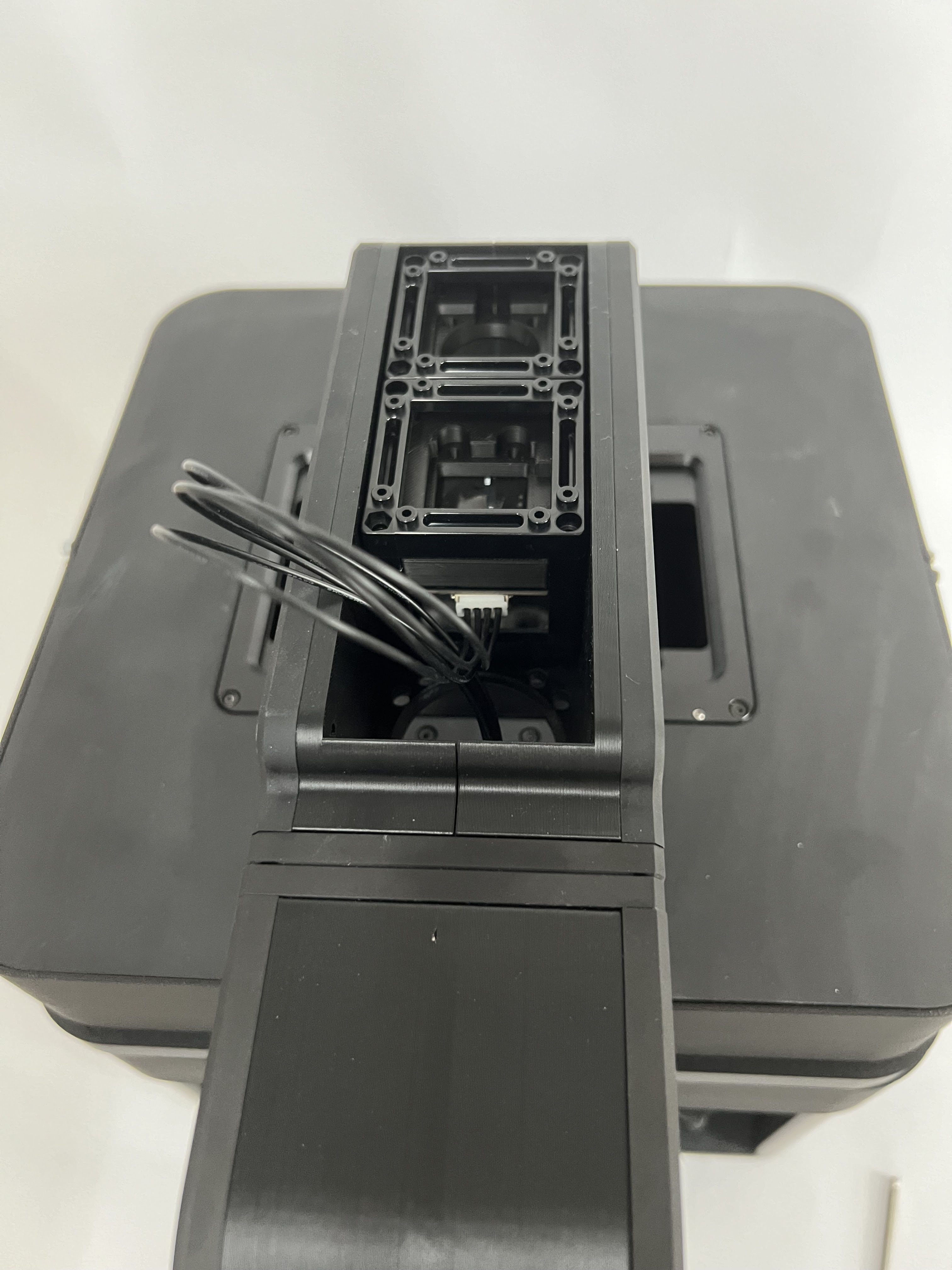
 Ensure the illumination arm is in its highest position
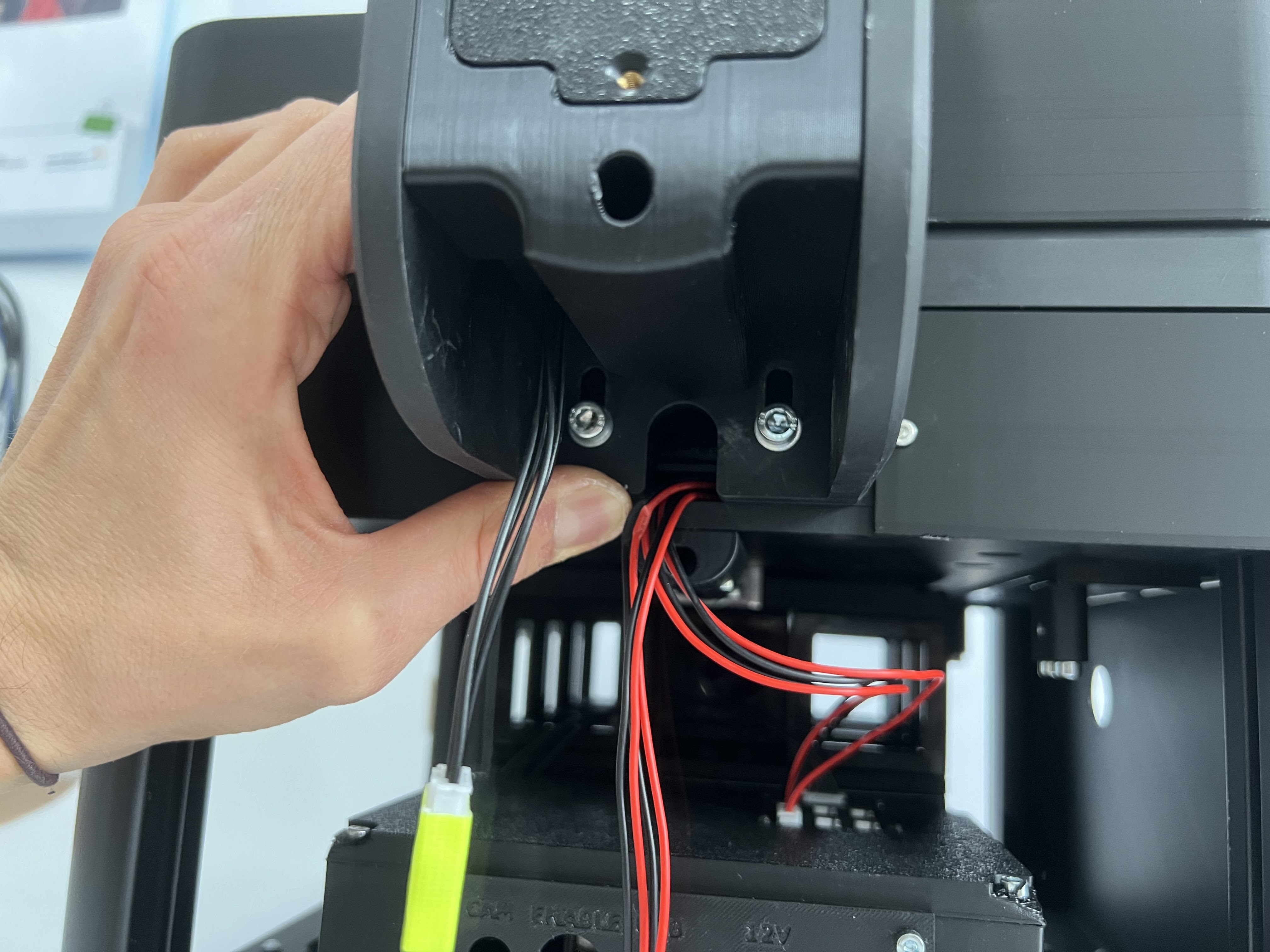
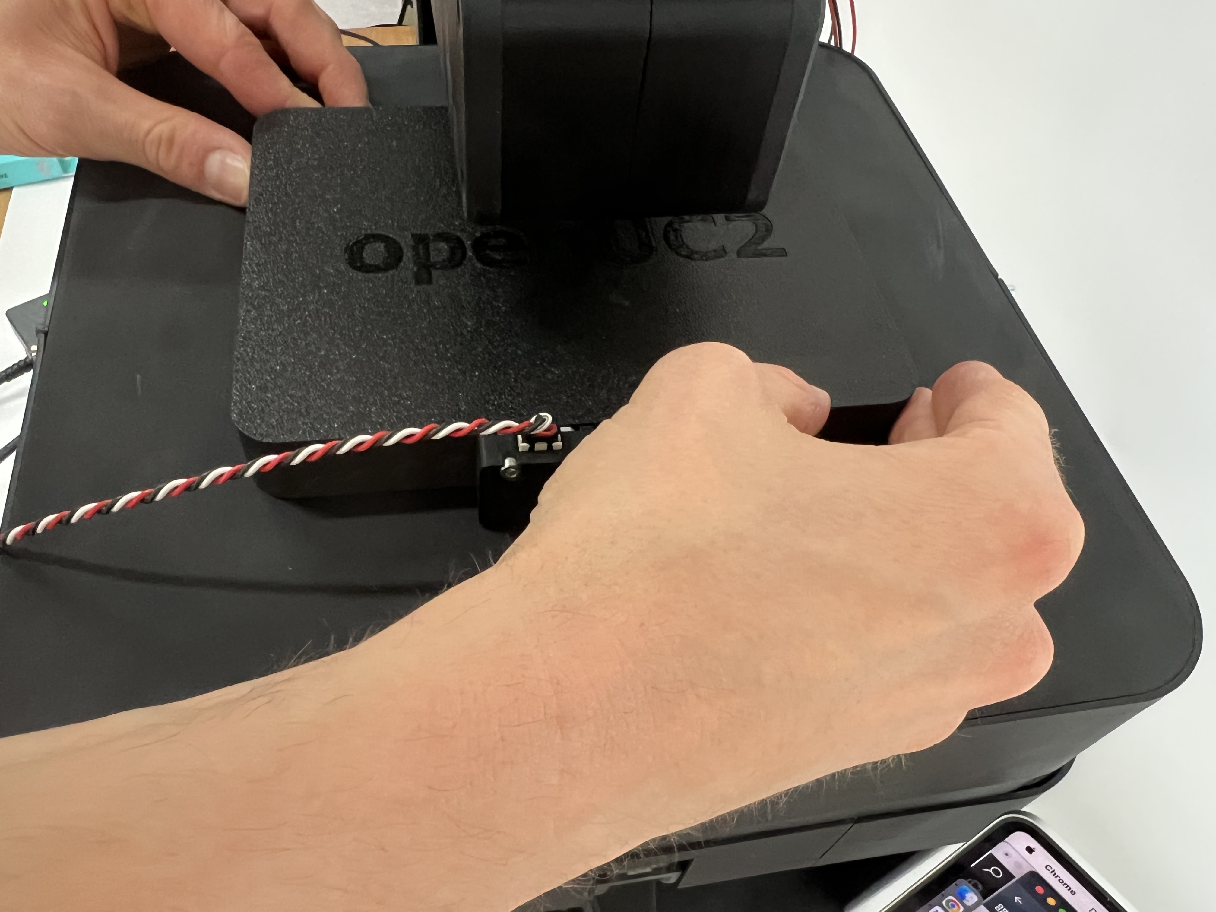
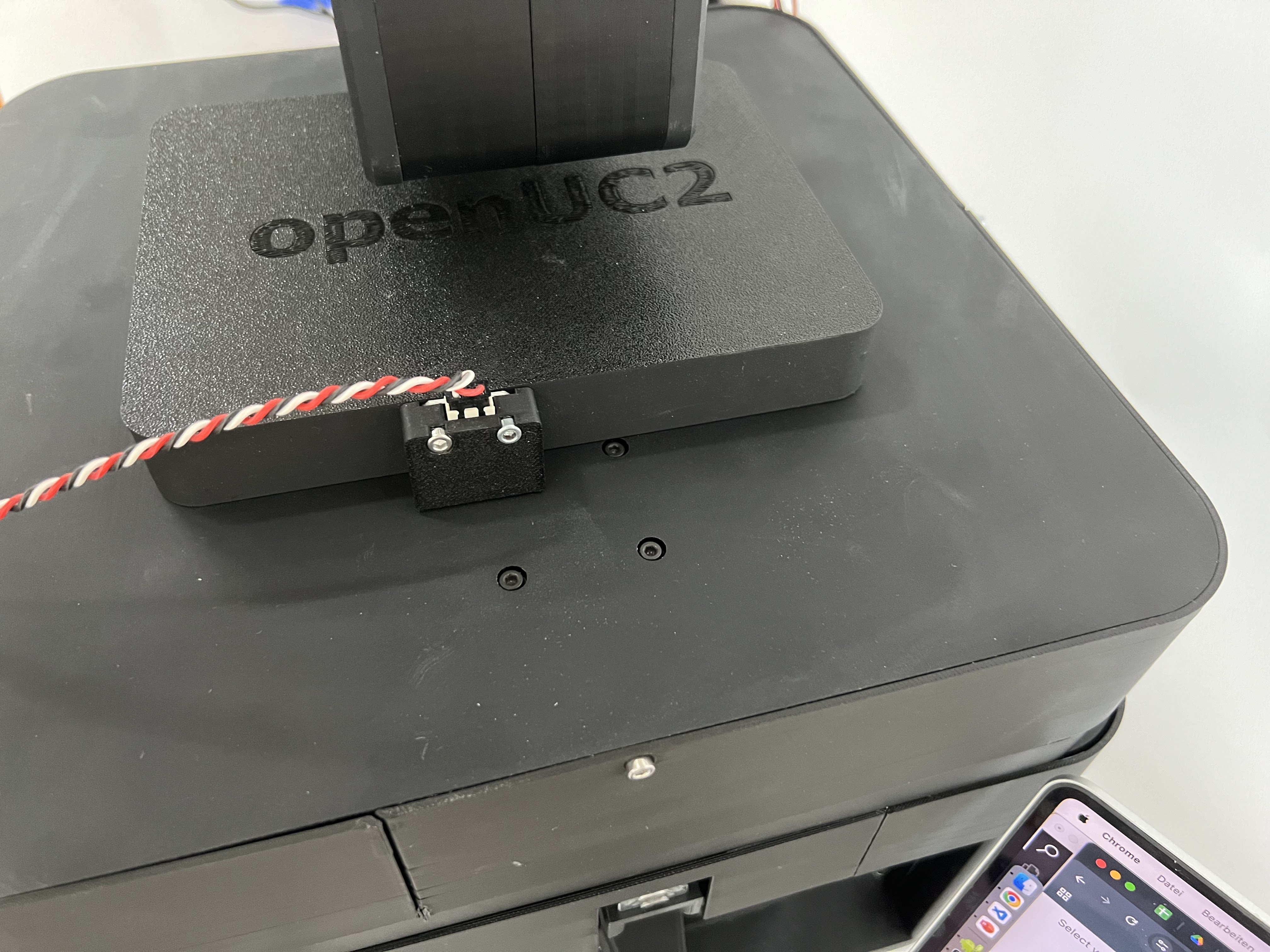
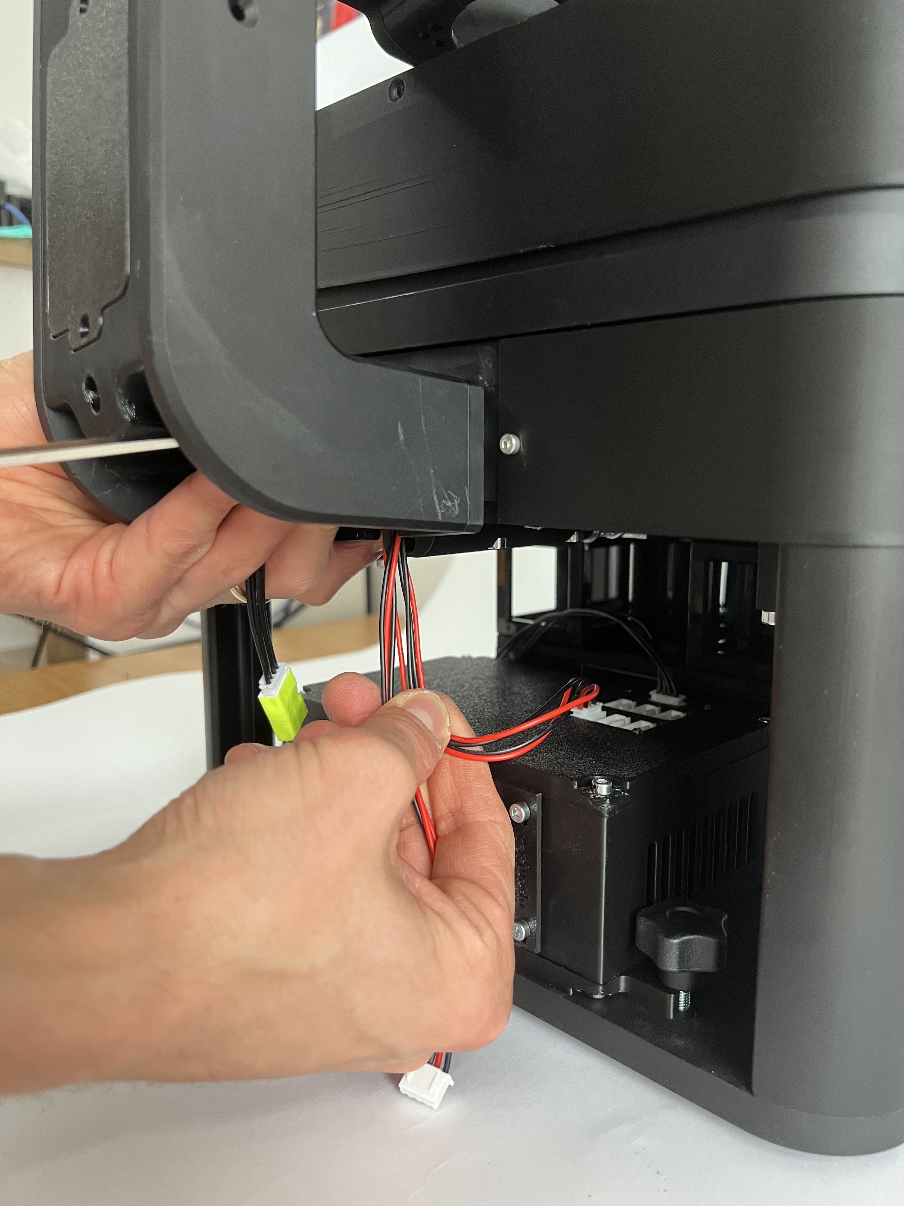 Attach the CAN bus cables from the illumination arm to the electronics board by plugging them into the junction board
 Secure the cable and optionally add the protective lid
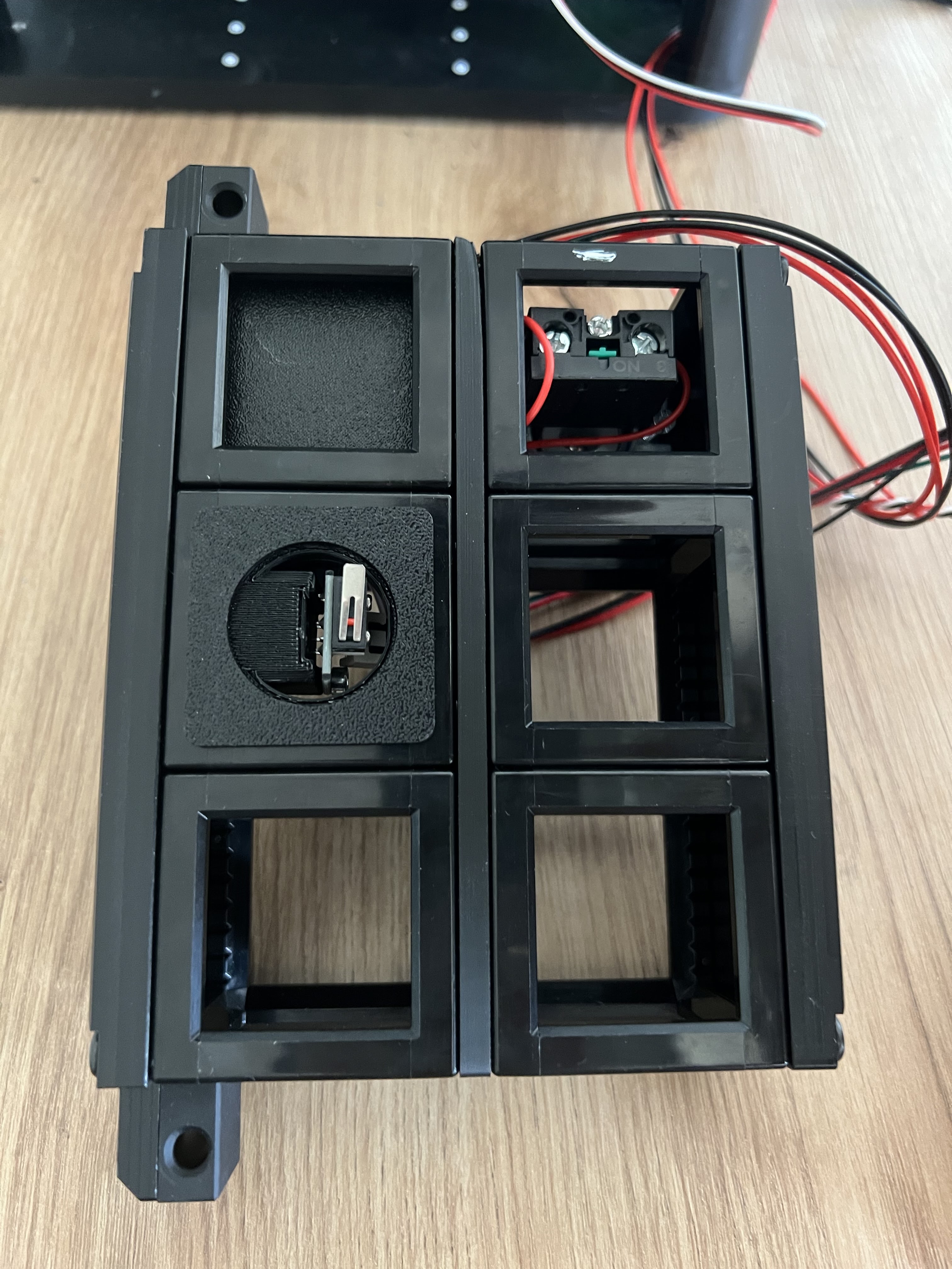
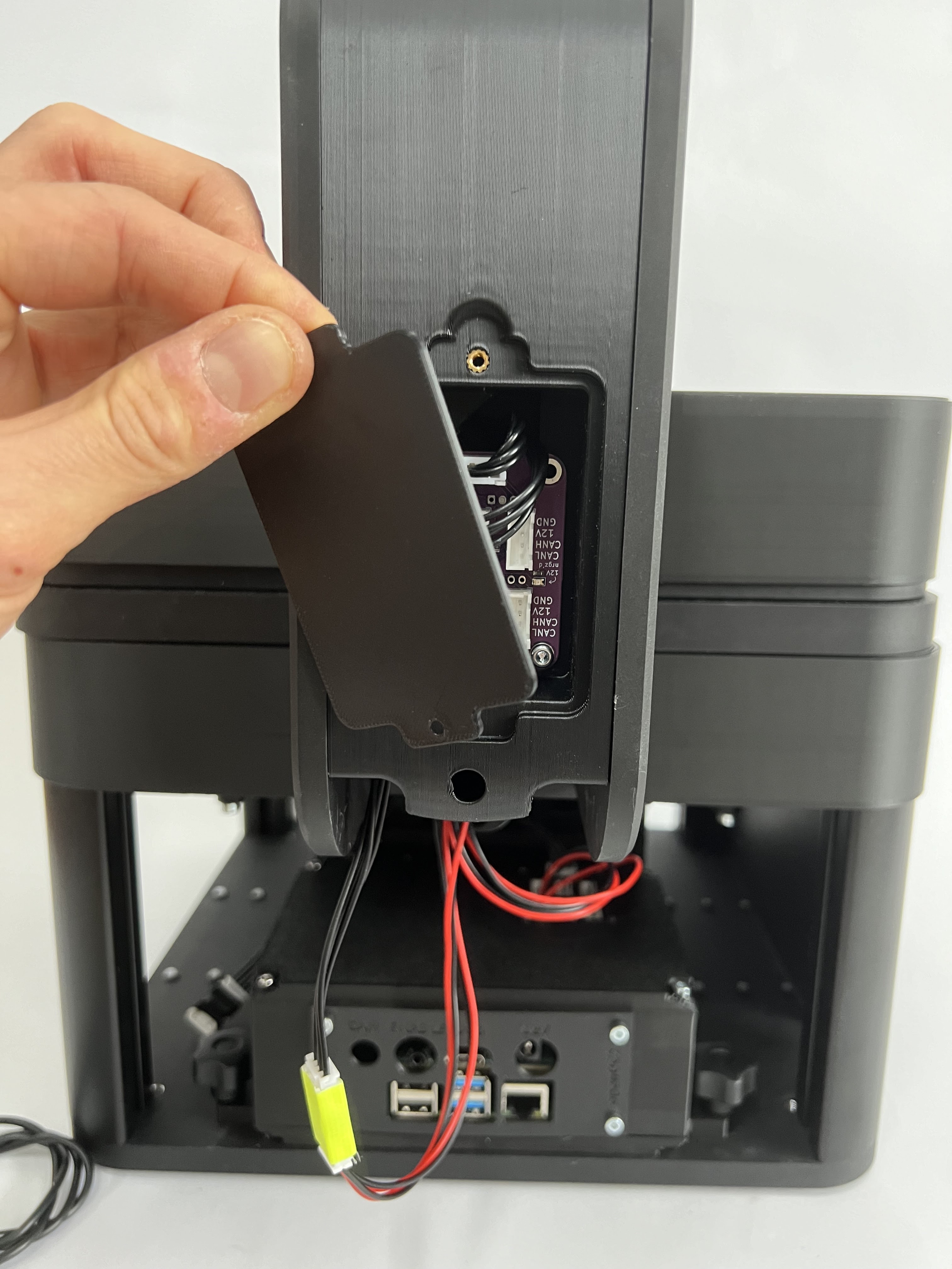 Opening the rear box unveils the CAN Relay board which can be used to add additional components like Motors, etc
Getting electronics to work
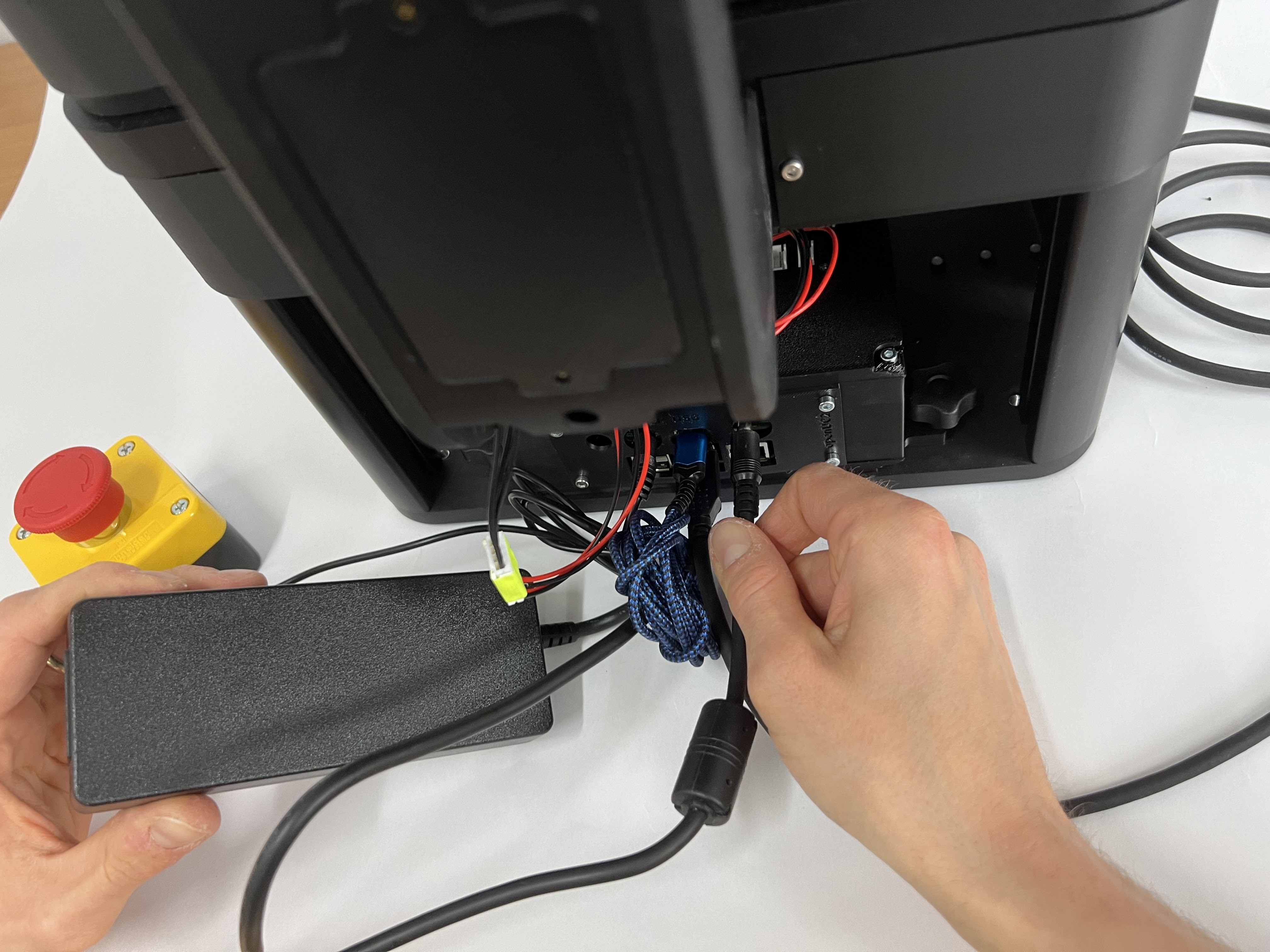
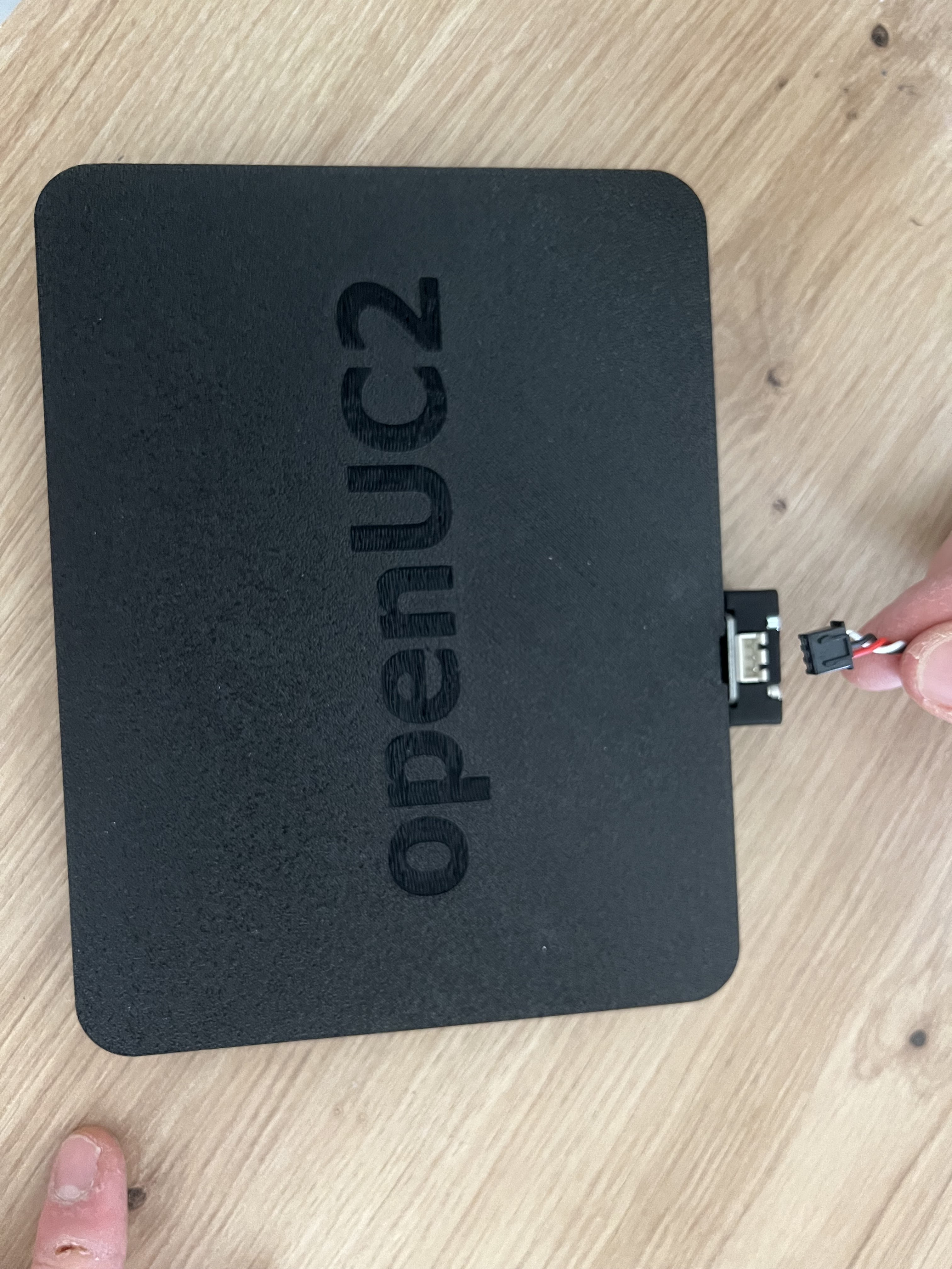
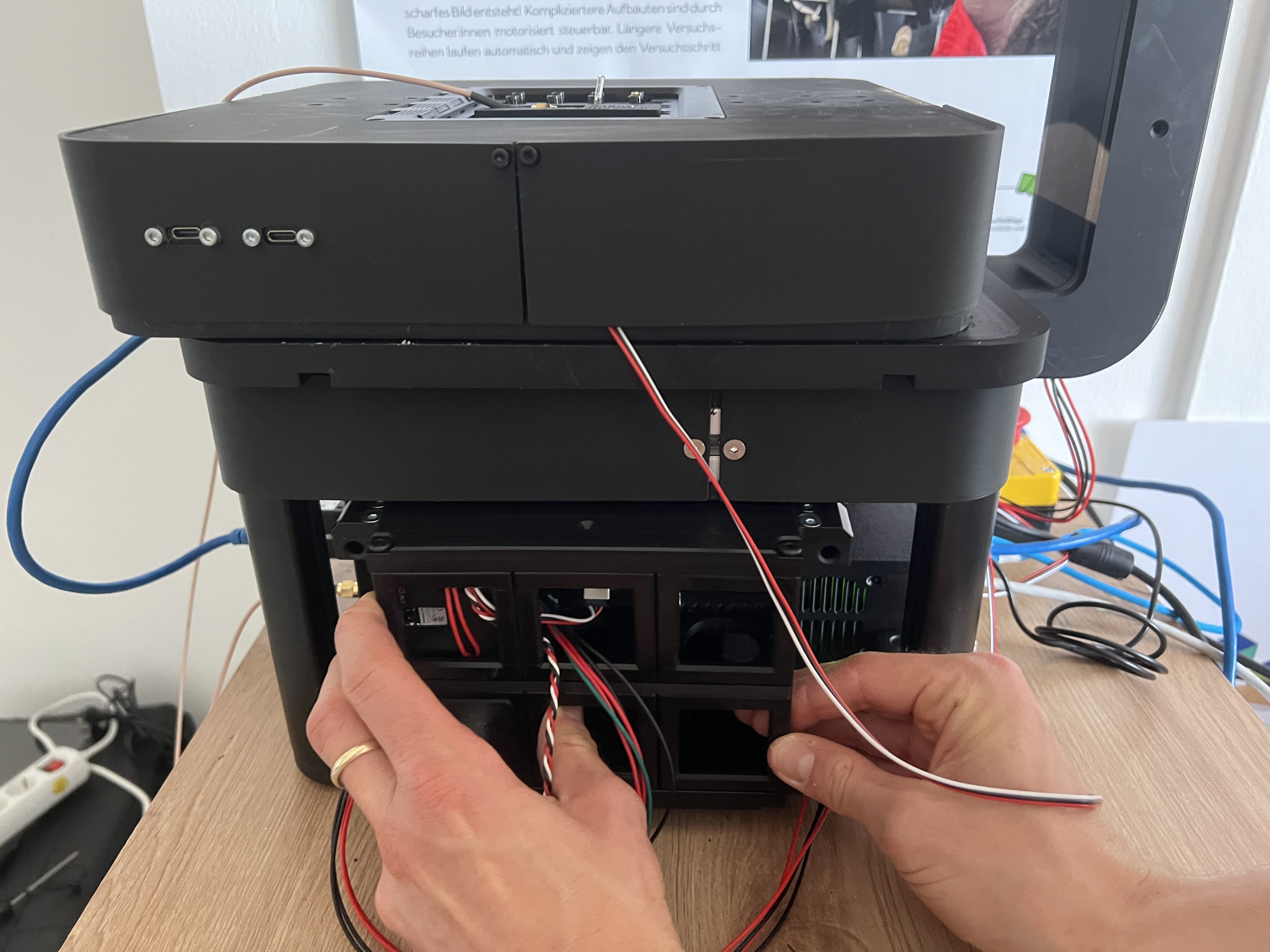
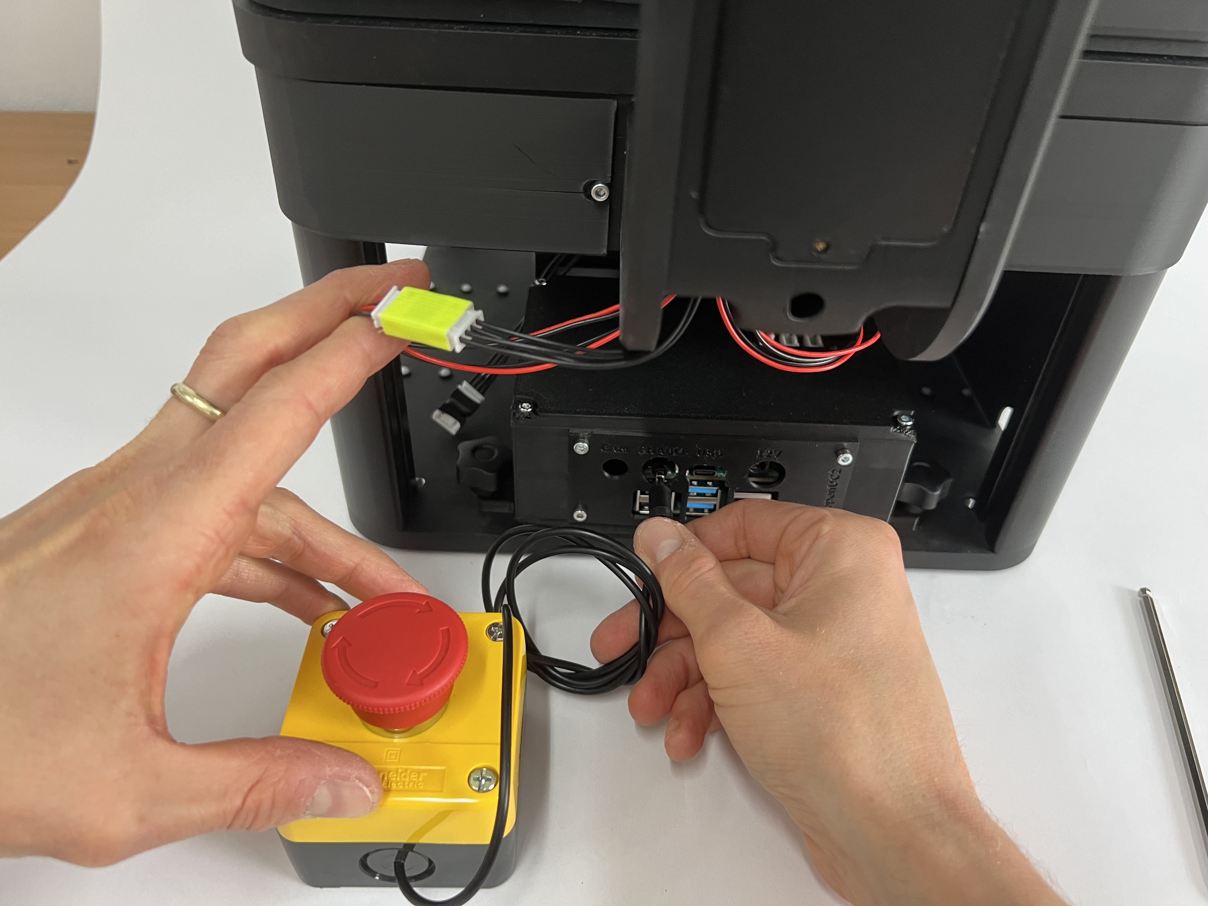 Plugging in the Emergency stop (Audio Jack) into the rear electronics that controls the microscope. Plug it into the slot with the audio jack that says emergency stop. Activate the emergency stop by pressing it
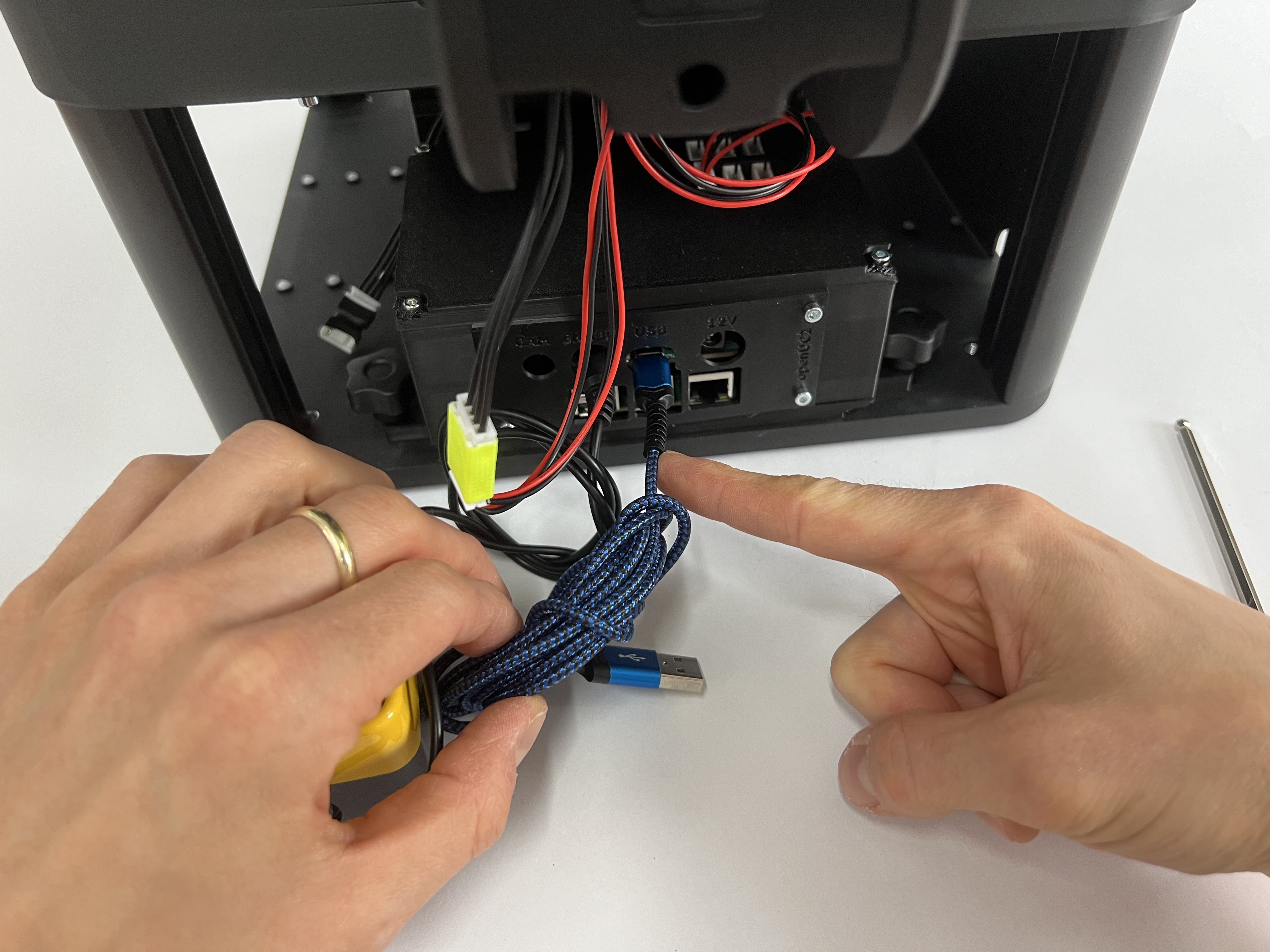 Connect the ESP32 control board that runs the UC2 Firmware (youseetoo.github.io) with the Raspberry Pi using the USB-C to USB-A cable (you can either use the blue USB3 or black USb2 slots)
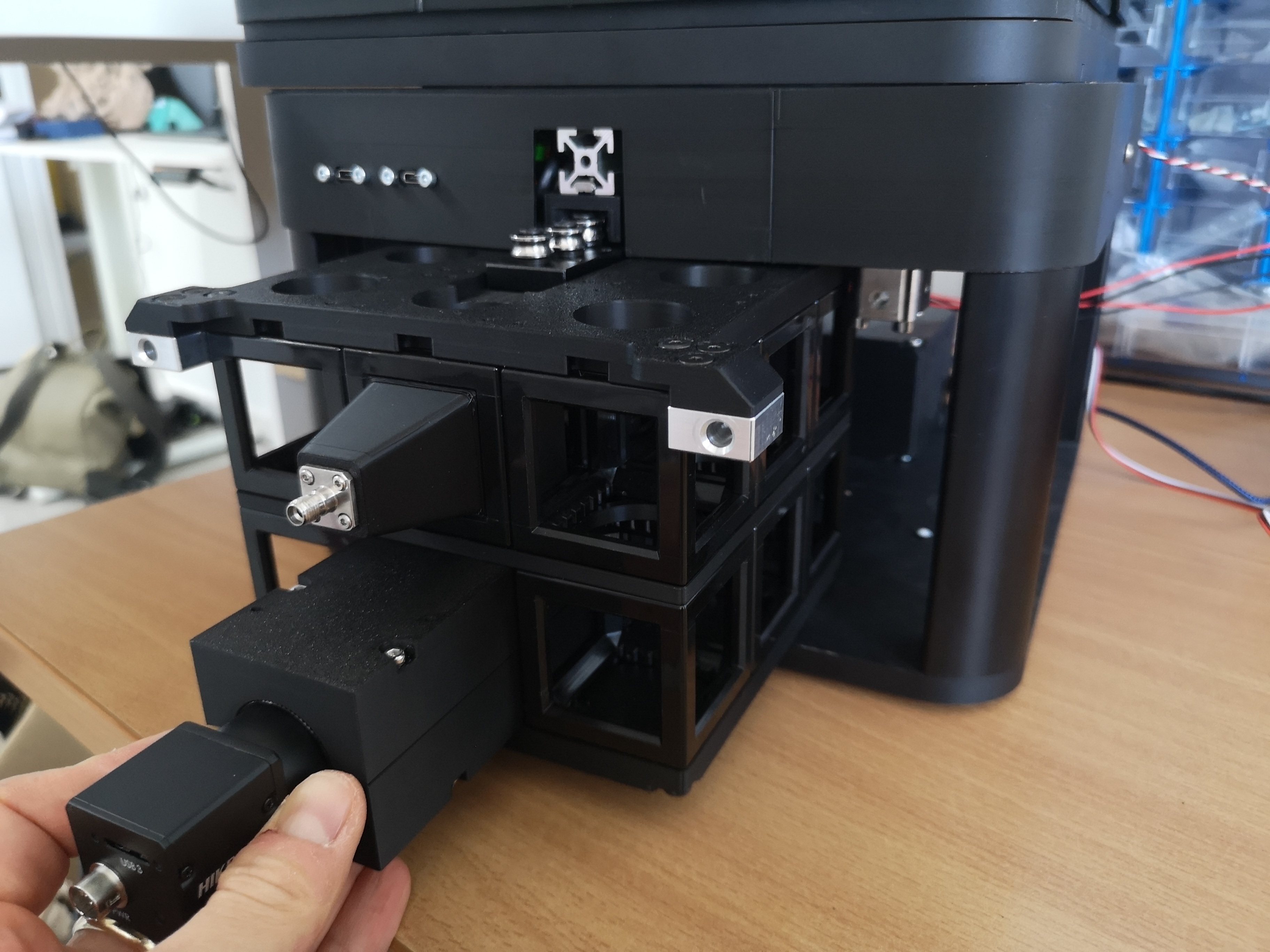
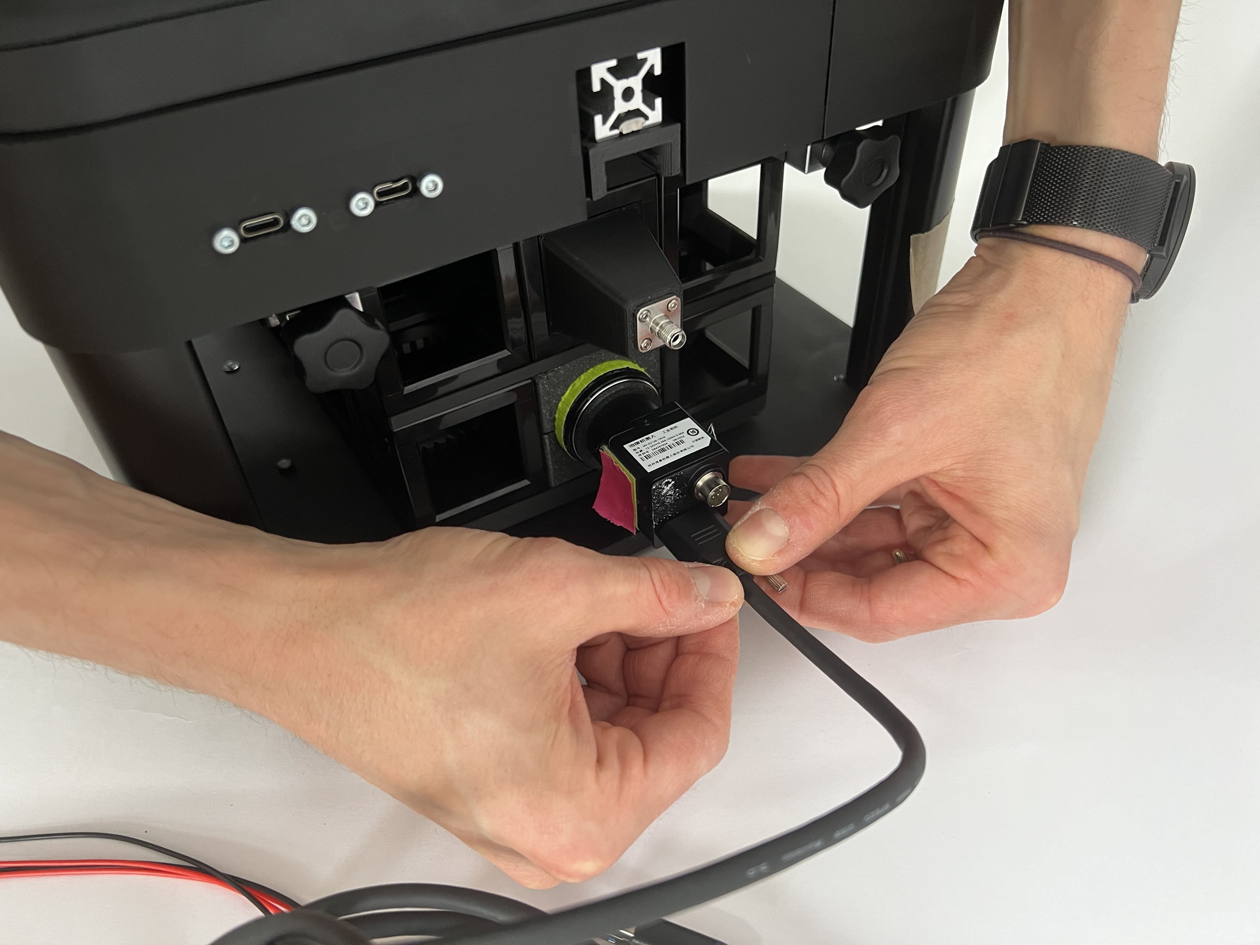 Mount the USB3 Camera cable and lock the screws on the camera side
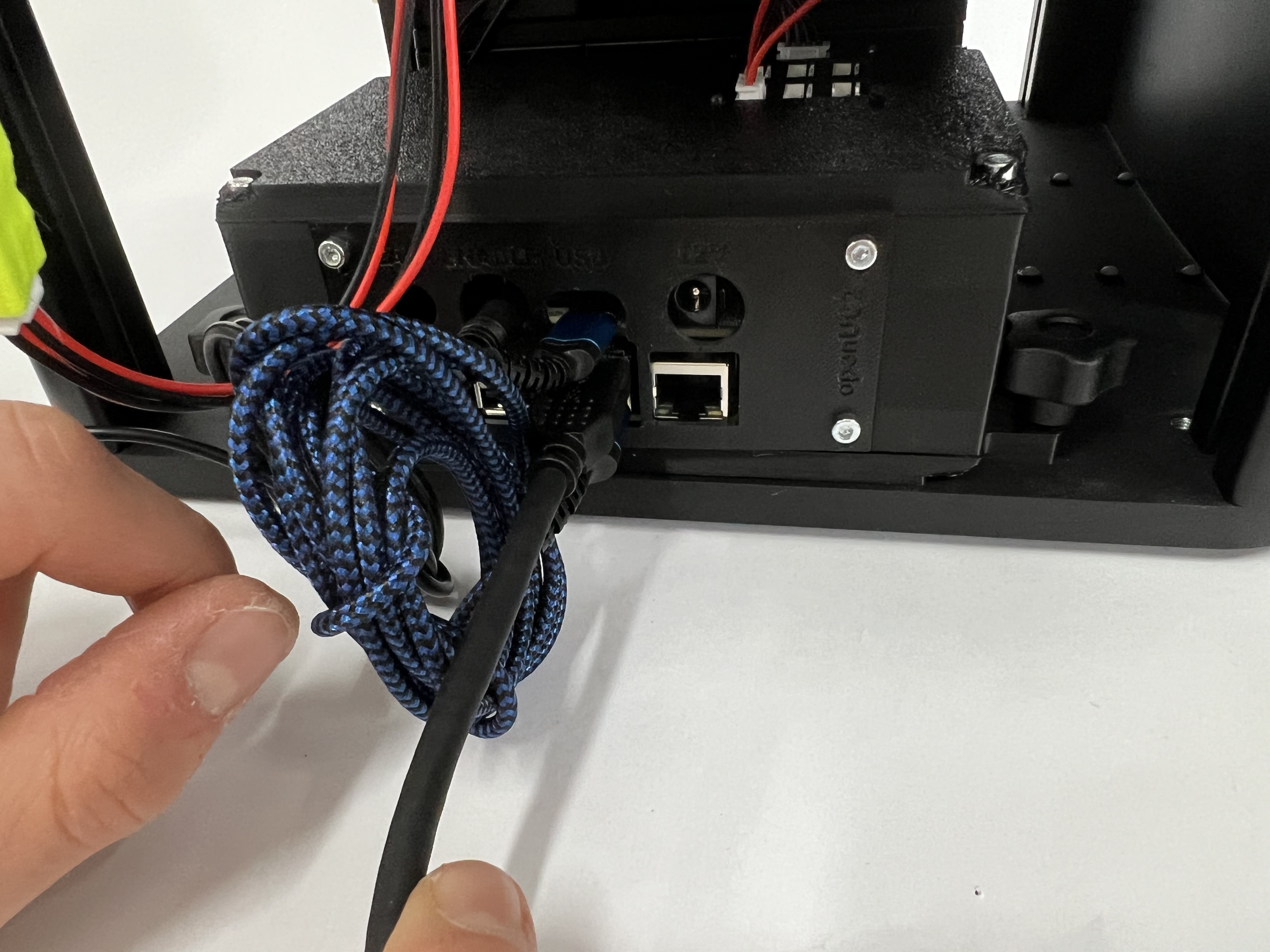 Mount the USb3 Camera cable on the Raspberry Pi side (use the blue USB3 slot)
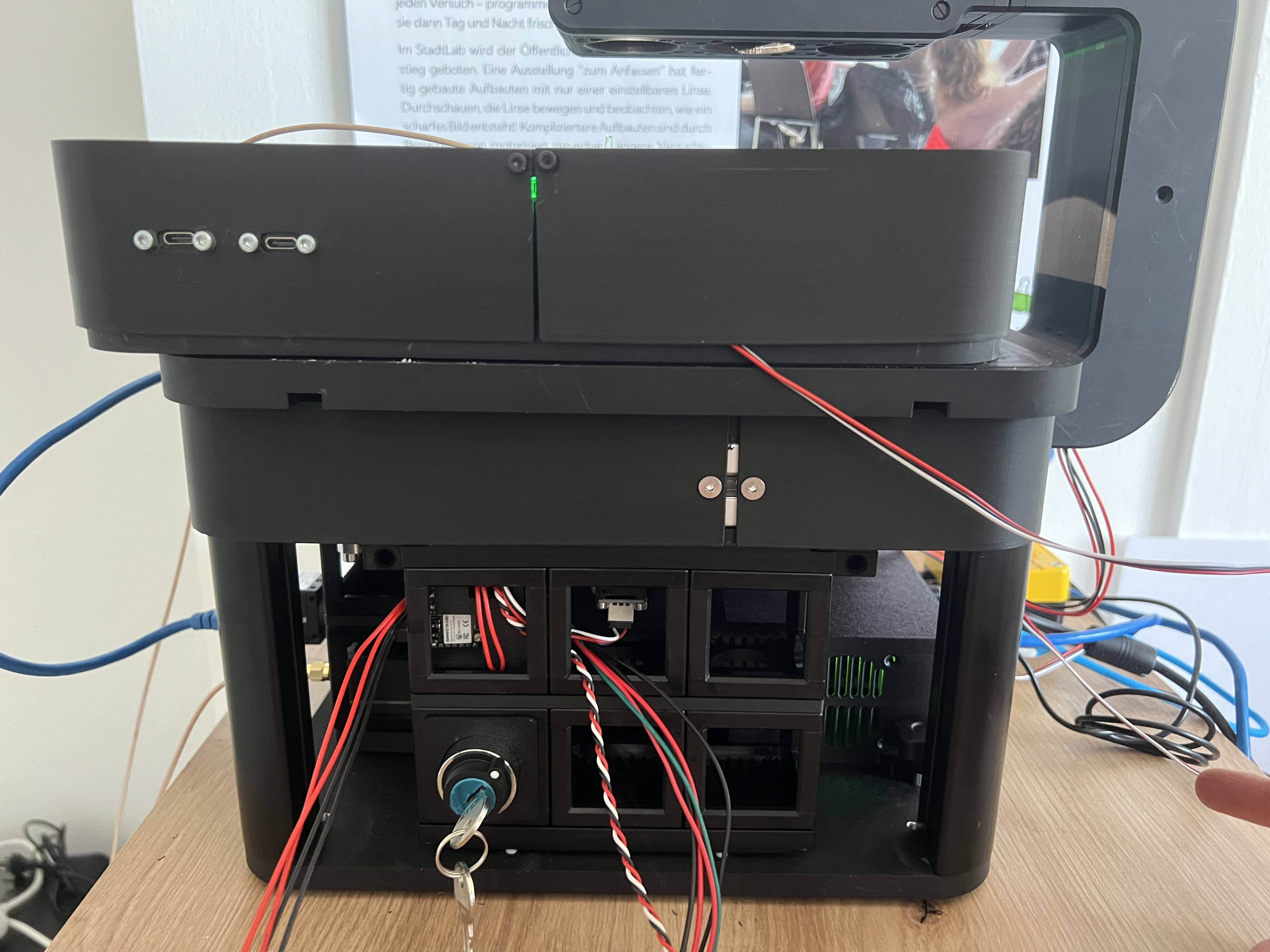
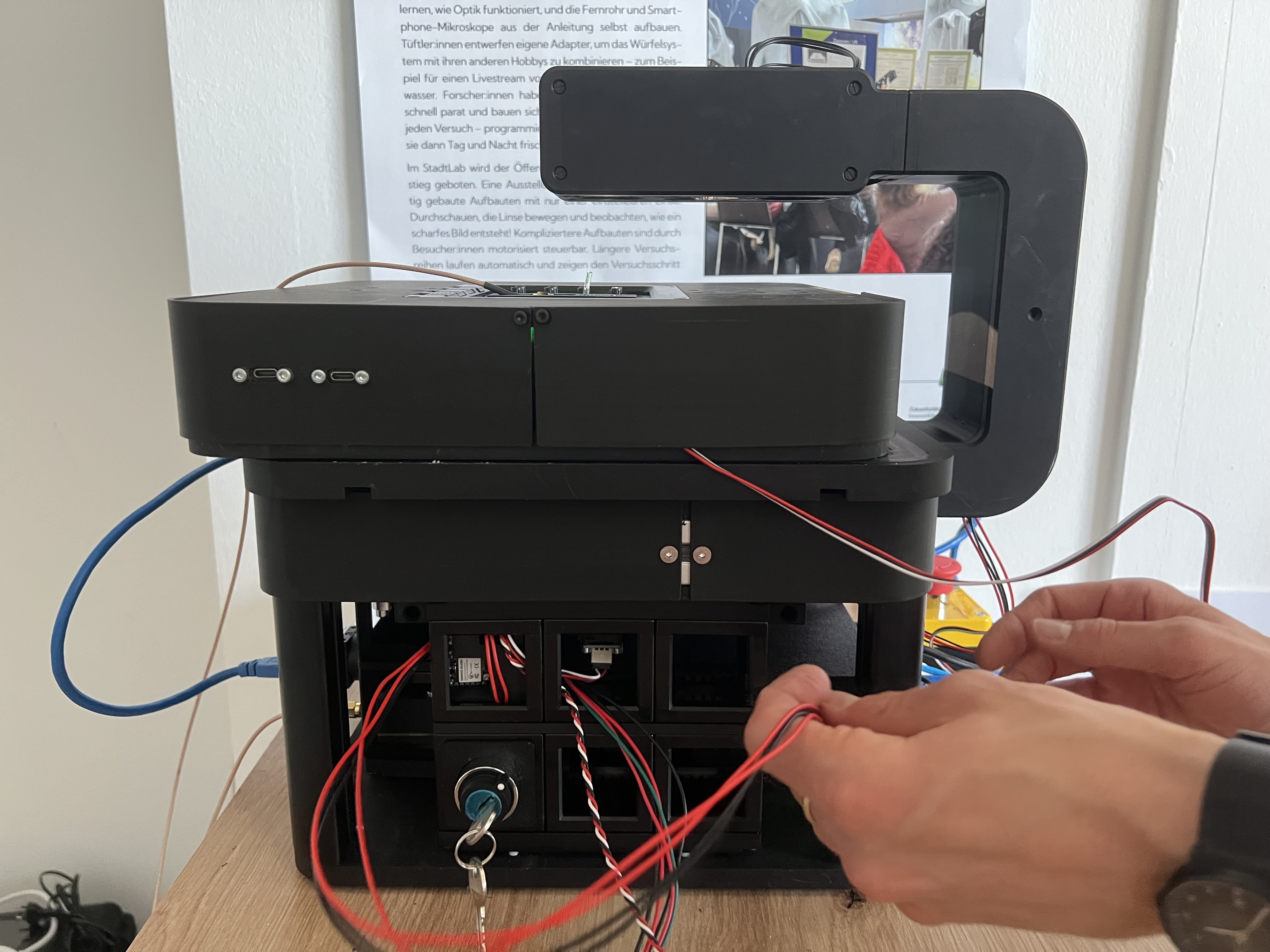
 Plug in the power suppy (12V) into the 12V jack on the Electronics side. Add the power socket (110/230V) cable and add this to the wall socket
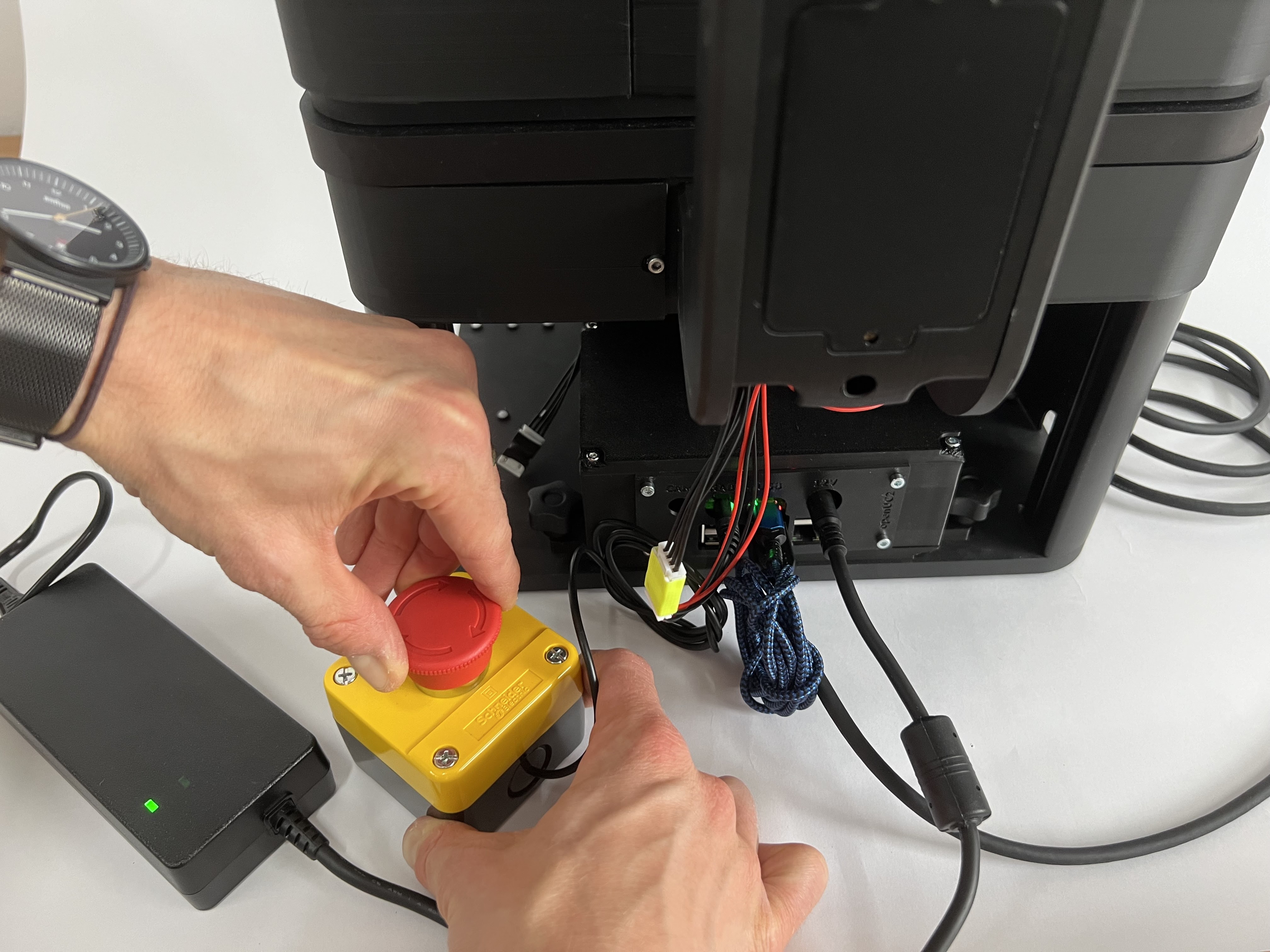 Release the emergency stop to add 12V to the Frame
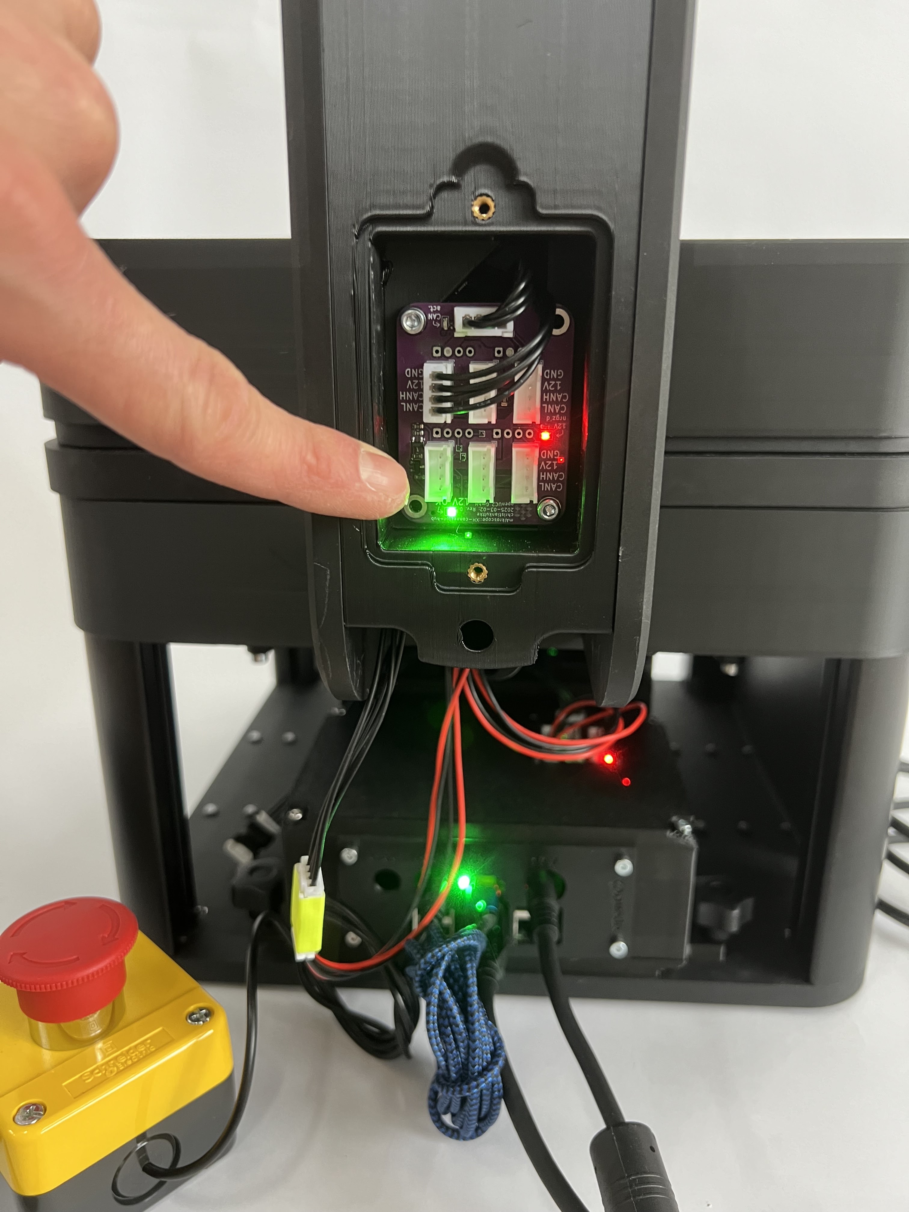 The power indicators on the relay boards should show 12V by letting the green LED light up
Initial System Testing
The PS4 controller and web interface operations are covered in detail in the Operation Manual.
System Function Tests
Mechanical Systems:
- Test all axis movements (X, Y, Z, A)
- Verify position accuracy and repeatability
- Check travel limits and home positions
- Test emergency stop functionality
Electrical Systems:
- Verify power indicators (green LEDs)
- Test CAN bus communication
- Check camera connectivity and image acquisition
- Confirm illumination control
Mounting Optics
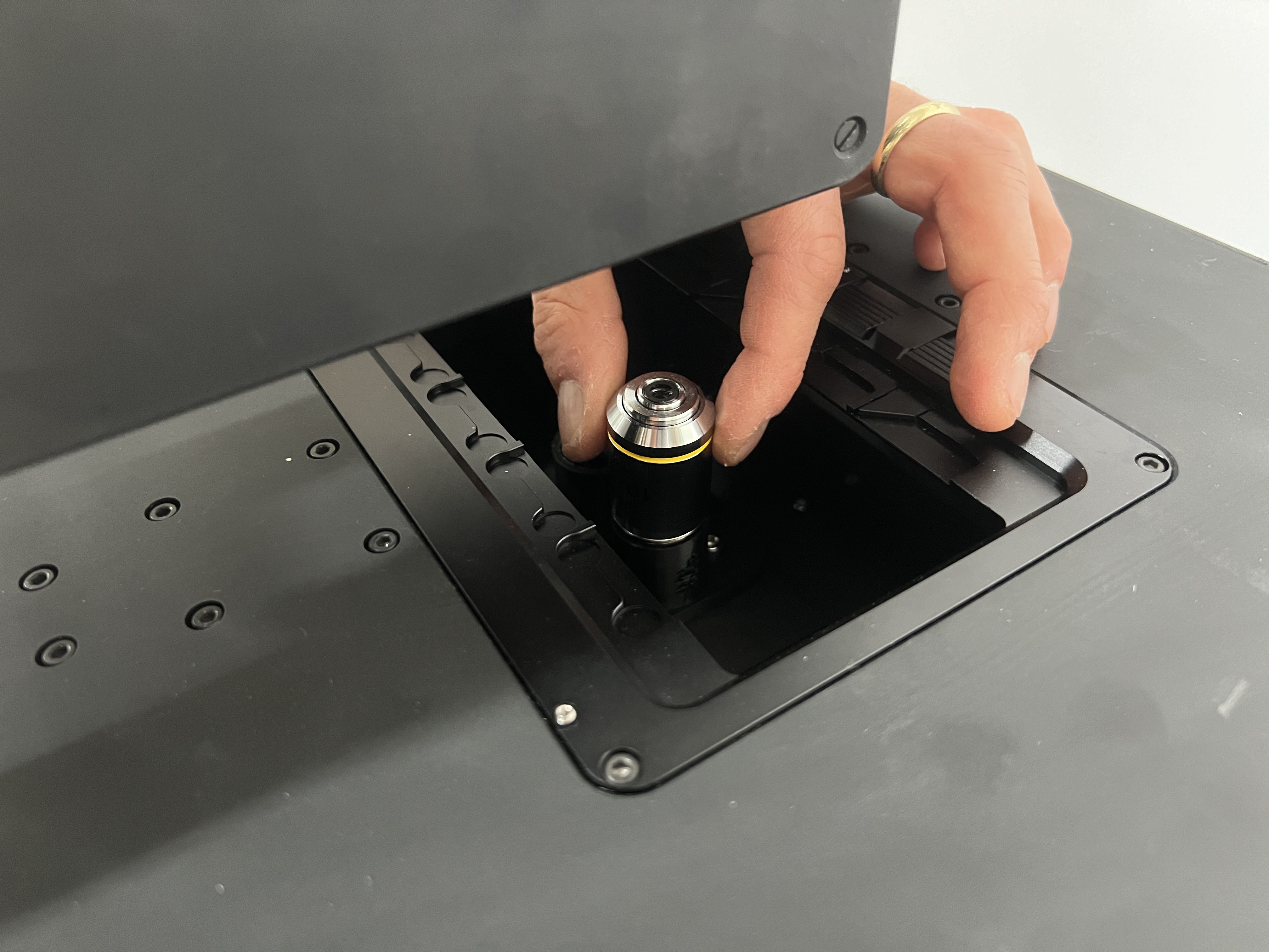 Unbox the objective lenses and insert them in the dedicated slots by screwing them into the RMS Threads. Remove the stickers from the objective mounts before. Be careful not to touch the surfaces
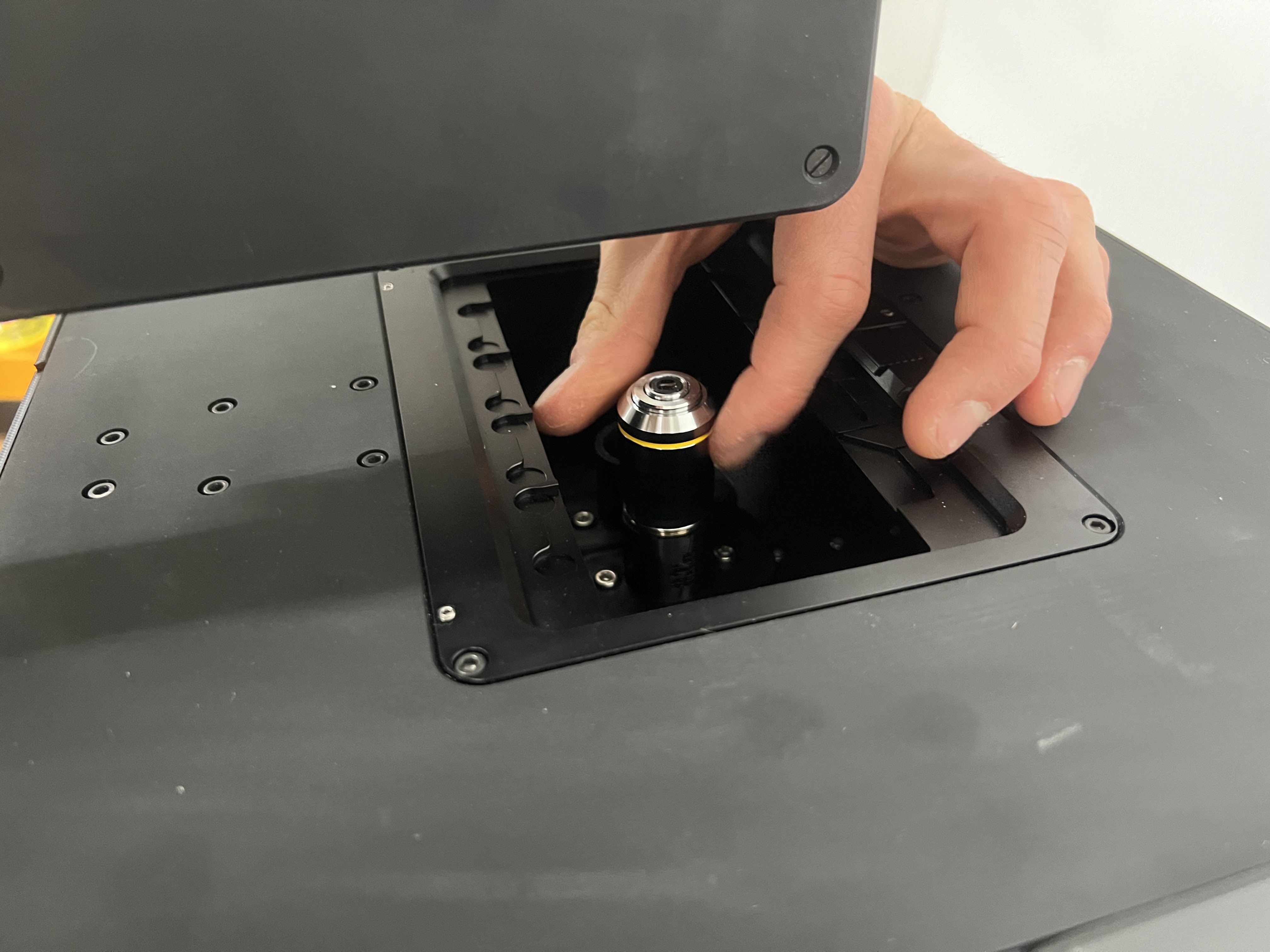 Do the same for objective #2. The order depends on the configuration you have and must be mirrored in the configuration file.
Configuration File Setup
The objective order and other system parameters must be properly configured in ImSwitch. A complete sample configuration file is provided at:
📁 Configuration File: config_examples/FRAME_ImSwitch_Configuration.json
This configuration file contains:
- Camera settings and detection parameters
- Laser and LED configurations
- Stage positioning and movement parameters
- Objective definitions and magnifications
- Available widgets and software components
You can also reference the online configuration repository: 🔗 https://github.com/openUC2/ImSwitchConfig/blob/master/imcontrol_setups/FRAME2.json
Software Installation and Configuration
Prerequisites
Before installing software locally, note that FRAME systems can be operated via:
- Web Interface: Direct browser access to the Raspberry Pi (recommended for most users)
- Local Installation: Install ImSwitch locally for advanced users or development
Local Software Installation (Advanced Users)
If you need to install ImSwitch locally on your computer:
Driver Installation:
- Install camera drivers (HikVision or compatible)
- Install motor controller drivers (ESP32-based)
- Install communication interface drivers (CAN-BUS/USB)
- Verify device manager shows all devices properly
Control Software Installation:
- Download latest ImSwitch software from GitHub
- Install UC2-REST API components
- Configure system parameters using provided configuration files
- Load device configuration files (see config_examples/)
Initial Configuration
Hardware Configuration:
- Define axis orientations and directions (see coordinate system reference)
- Set travel limits and home positions
- Configure camera parameters (exposure, gain, etc.)
- Calibrate stage positioning using calibration target
User Interface Setup:
- Configure display preferences and layouts
- Set default acquisition parameters
- Create user profiles for different operators
- Configure safety interlocks and emergency stops
Laser Module Installation and Safety
Laser Safety Overview
⚠️ CRITICAL SAFETY INFORMATION
Laser safety is paramount when working with the FRAME system. The device incorporates multiple safety mechanisms to ensure Class 1 laser operation, meaning no dangerous radiation can escape the device enclosure when properly assembled.
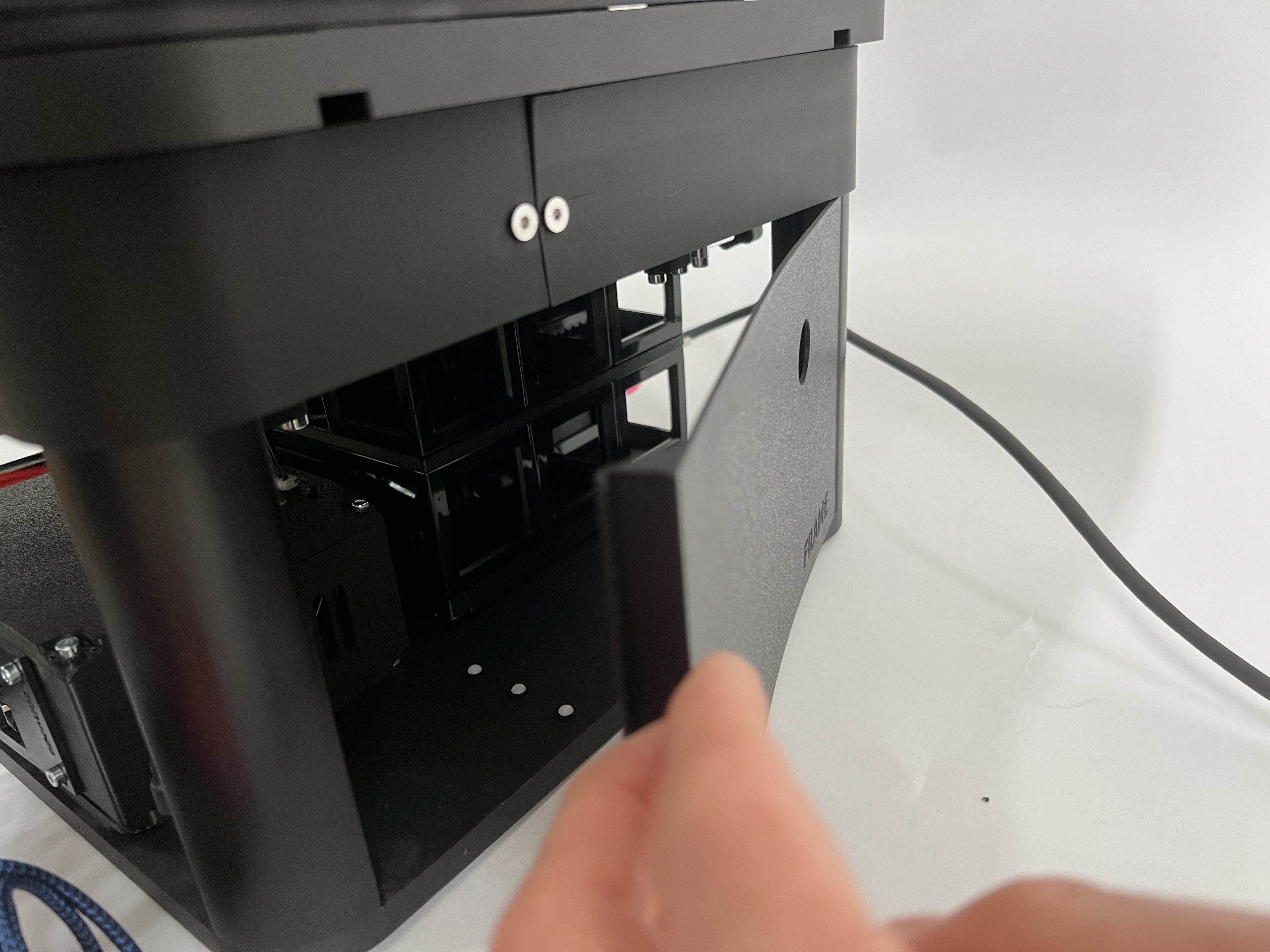 add the laser cover at the side
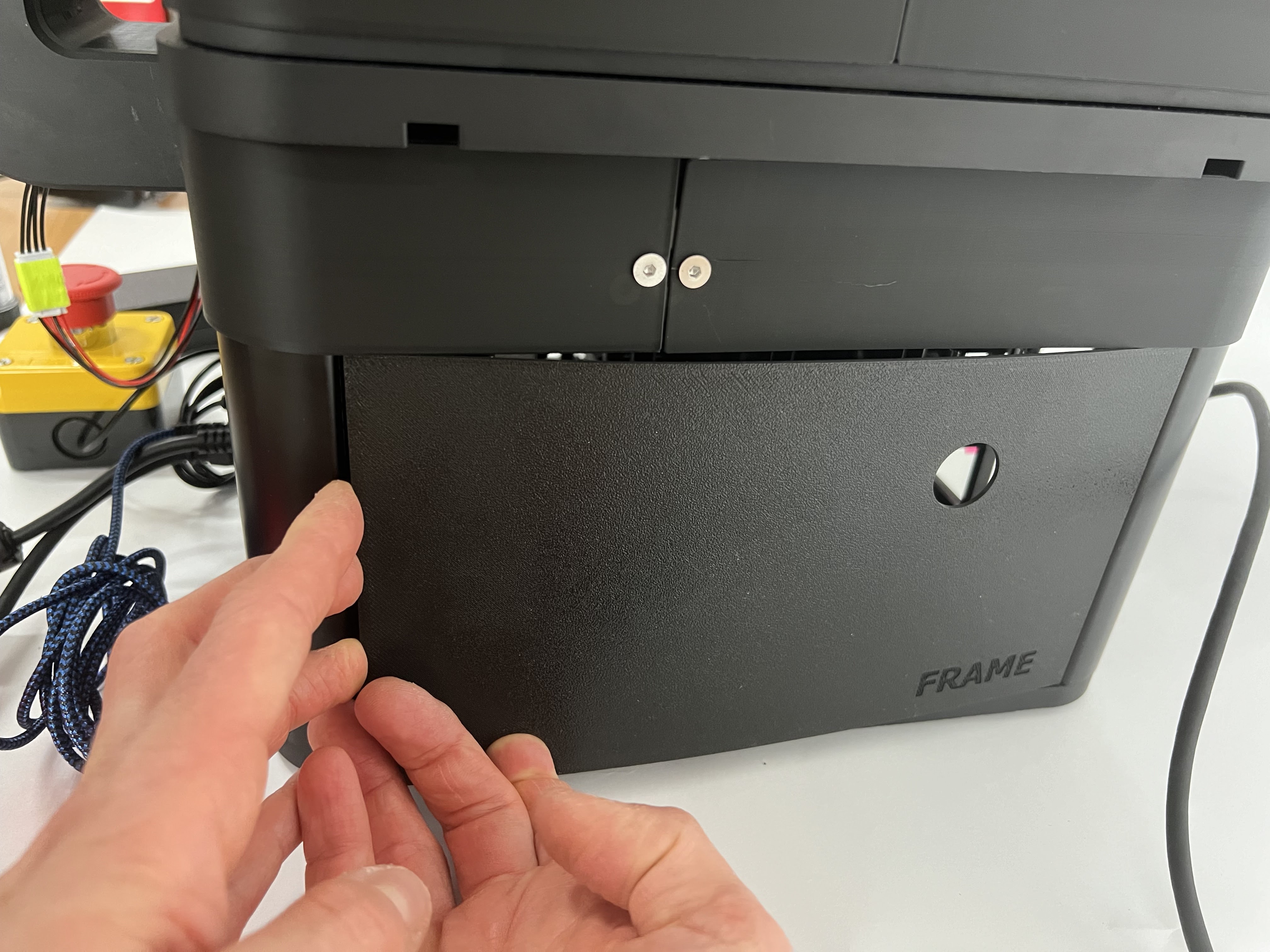 Secure the laser cover by snapping it in place
Safety Mechanisms
The FRAME incorporates three primary safety systems:
Sample Lid Interlock:
- Laser-blocking lid with integrated safety switch
- Must be properly positioned to activate laser systems
- Prevents light from escaping through the objective lens
Key Switch Interlock:
- Physical key switch that must be activated to enable laser operation
- Provides positive control over laser activation
Internal Interlocks:
- Monitors proper positioning of laser cover and internal components
- Automatically disables laser if components are not properly installed
Safety Procedures
Before Operating with Lasers:
- Familiarize yourself with all safety features
- Ensure all interlocks are functional
- Verify proper assembly of all safety components
- Check for any reflective surfaces in the beam path
- Ensure proper ventilation and lighting in work area
Emergency Procedures:
- In case of power loss or interlock interruption, lasers automatically shut down
- Use the key switch to clear interlocks after addressing any safety issues
- Contact support if any safety mechanism appears damaged
Laser Module Installation Procedures
Step 1: Prepare Laser Safety Lid
 Connect the laser safety lid cable to the interlock system
Step 2: Install Sample Safety Lid
 The laser safety cover attaches magnetically to the four mounting points on the sample stage. The safety switch activates only when the lid is properly positioned.
 Orient the openUC2 logo so it can be read when standing in front of the device
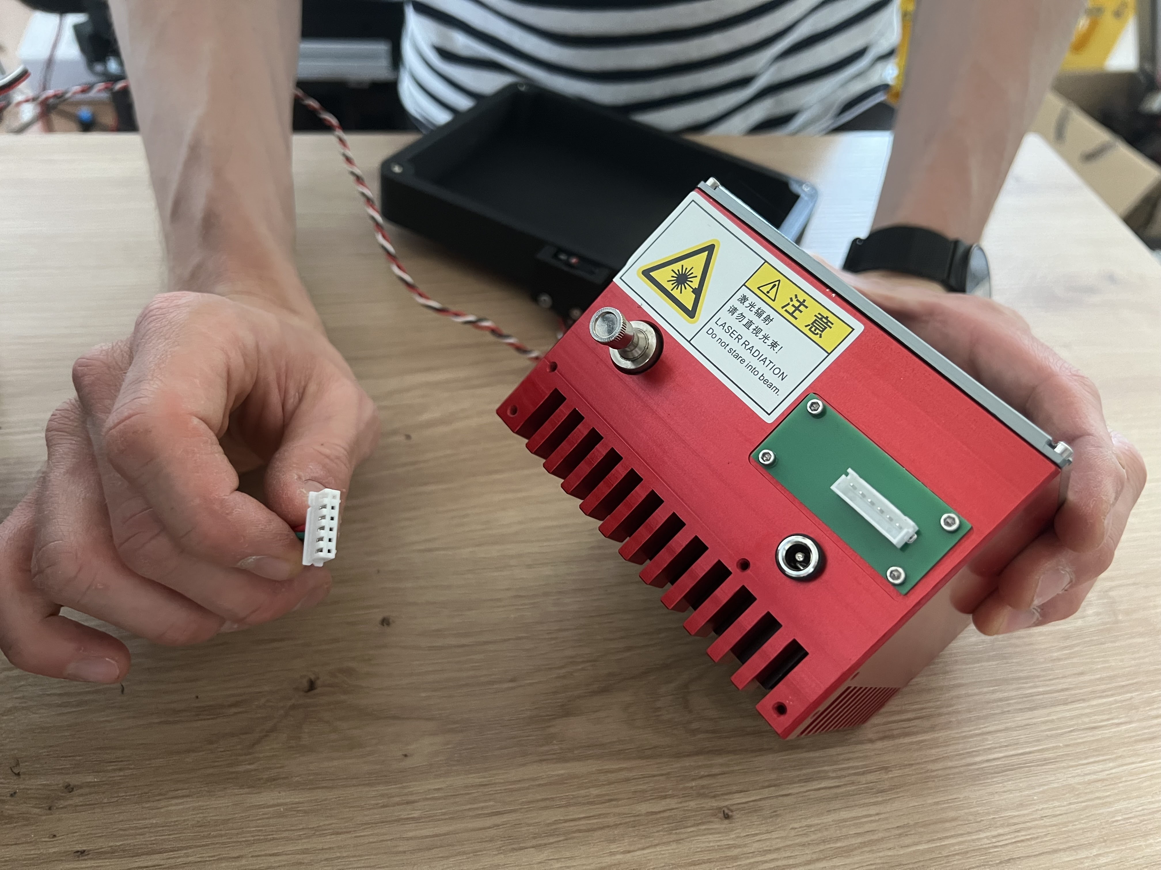
Step 3: Install Laser Module Assembly
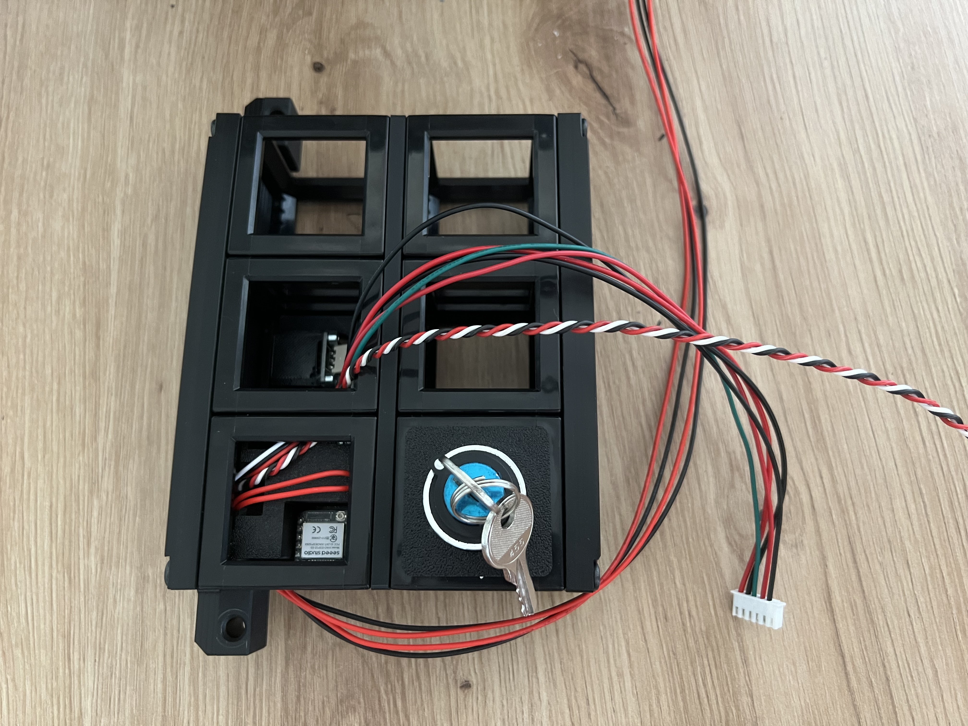 The laser interlock and control unit can be removed from the main body similar to the optics cube. It contains the CAN bus adapter and internal safety interlocks.
 Locate the internal laser interlock switch on the opposite side of the module
 Slide the laser module into position from the side
 Secure the laser module using the knurled locking screws
Step 4: Connect Laser Module
 Connect the laser module to the CAN bus using the provided cable
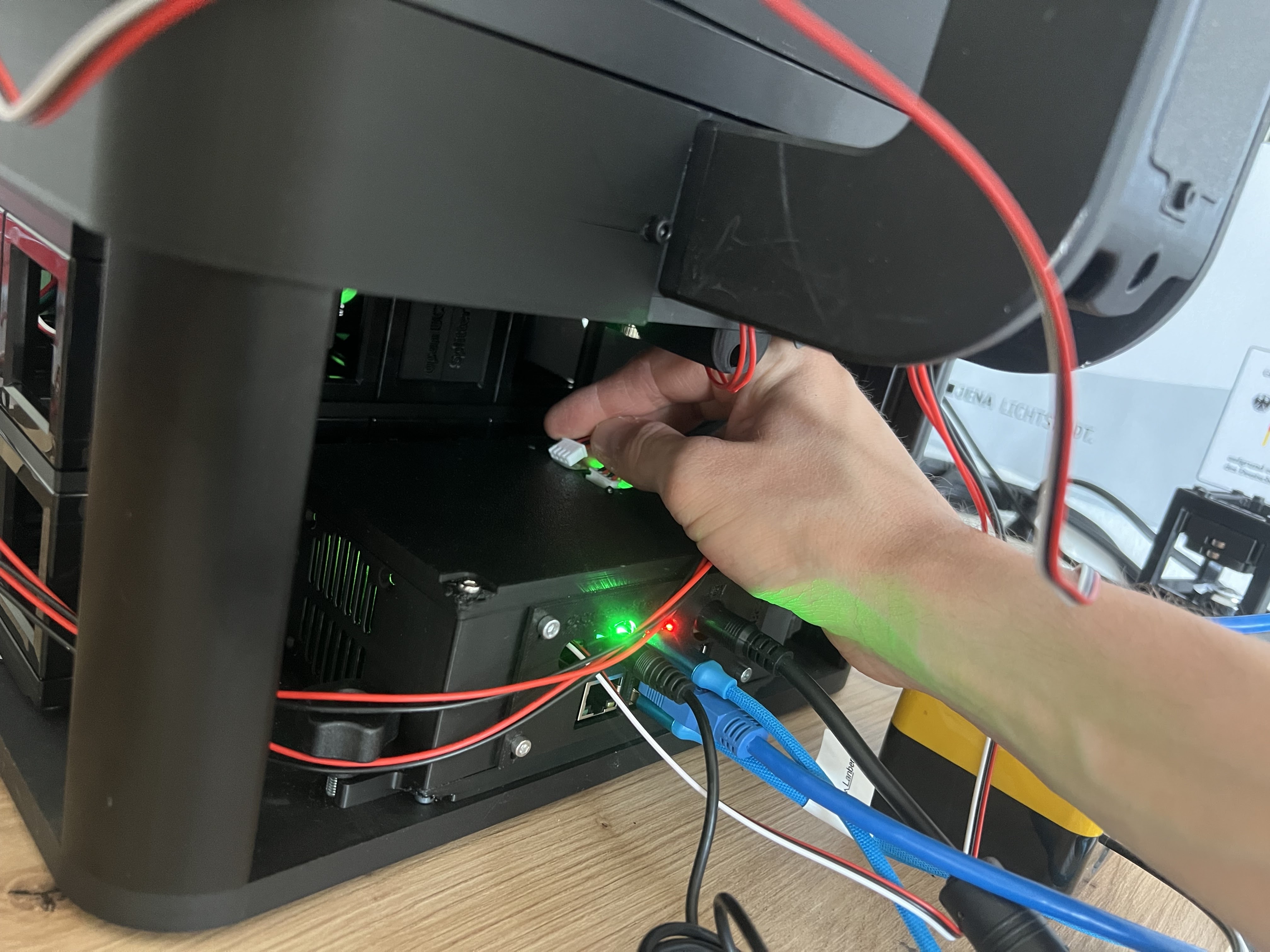 Connect the CAN bus cable to the electronics box similar to the illumination unit
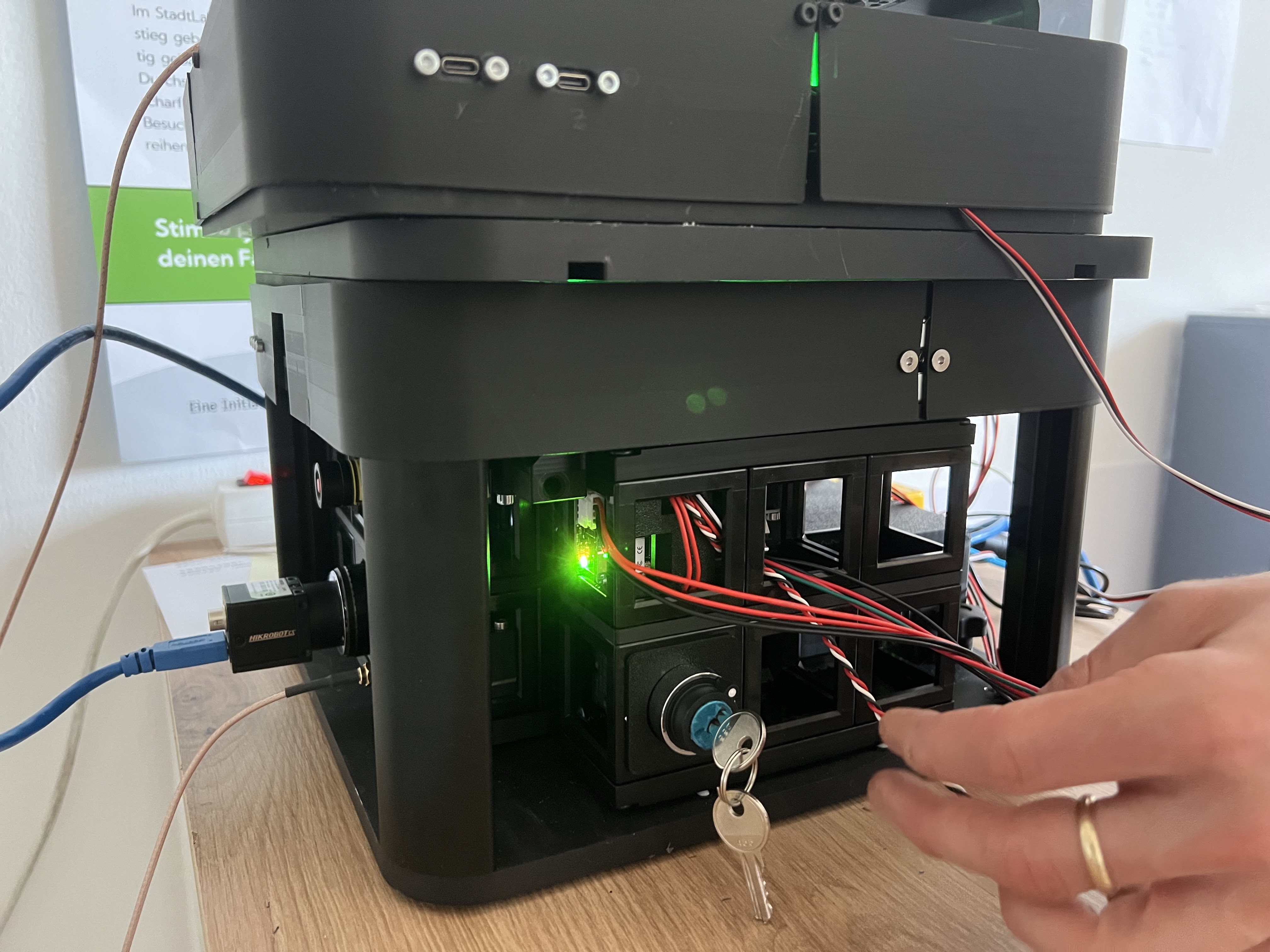 Power indicator: Green LED confirms the laser module is receiving power. The hardwired interlock system requires active key switch activation before laser operation is possible.
⚠️ SAFETY REMINDER: Before activating the key switch, ensure there are no unprotected reflective surfaces in the beam path that could redirect laser light.
Step 5: Laser Connection (External Laser Configurations)
Note: The following steps apply only to external laser configurations. Internal laser modules may not require these connections.
 Connect the laser control cable from the laser module to the external laser
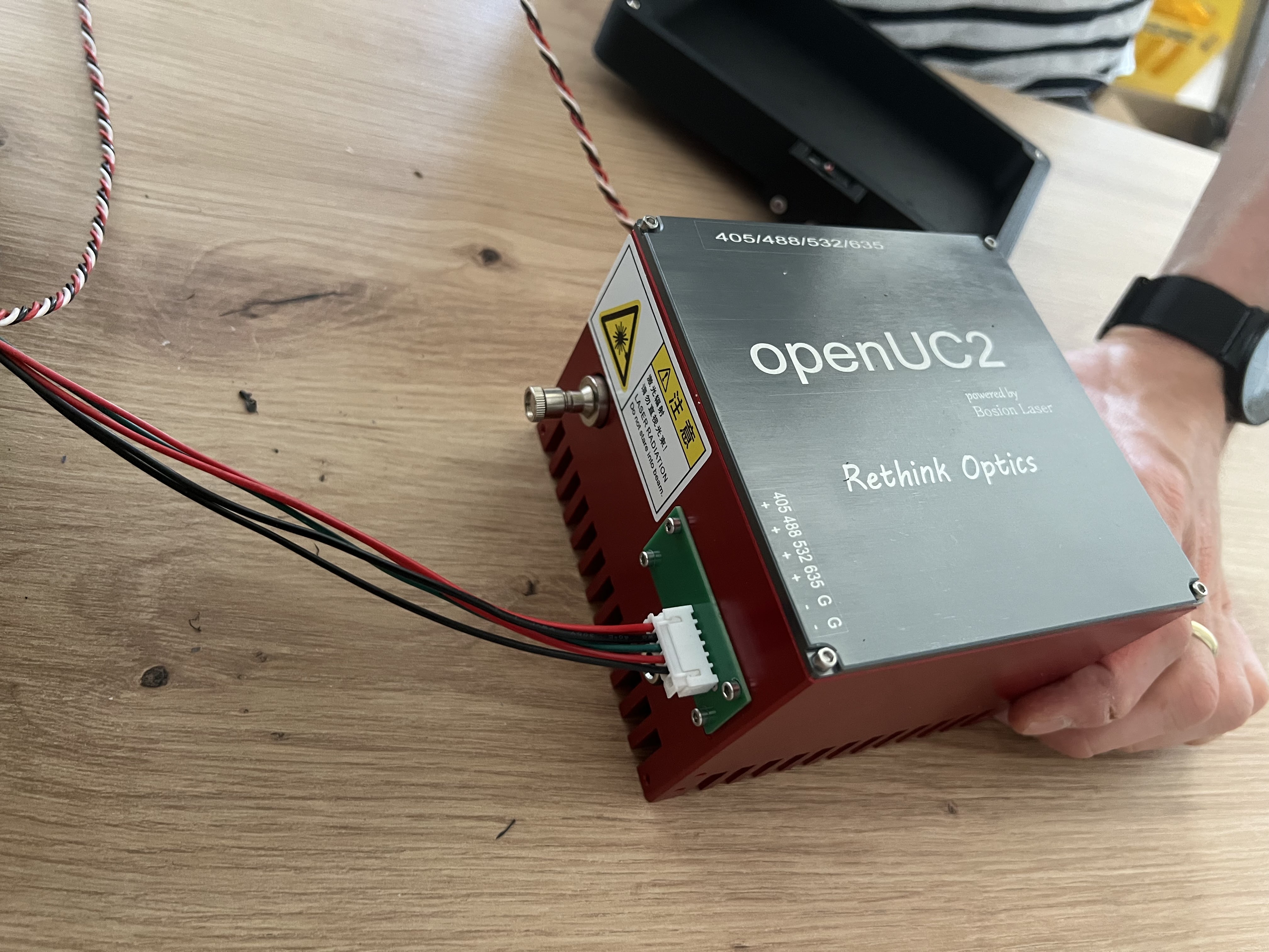 Verify correct wiring of the external laser control box
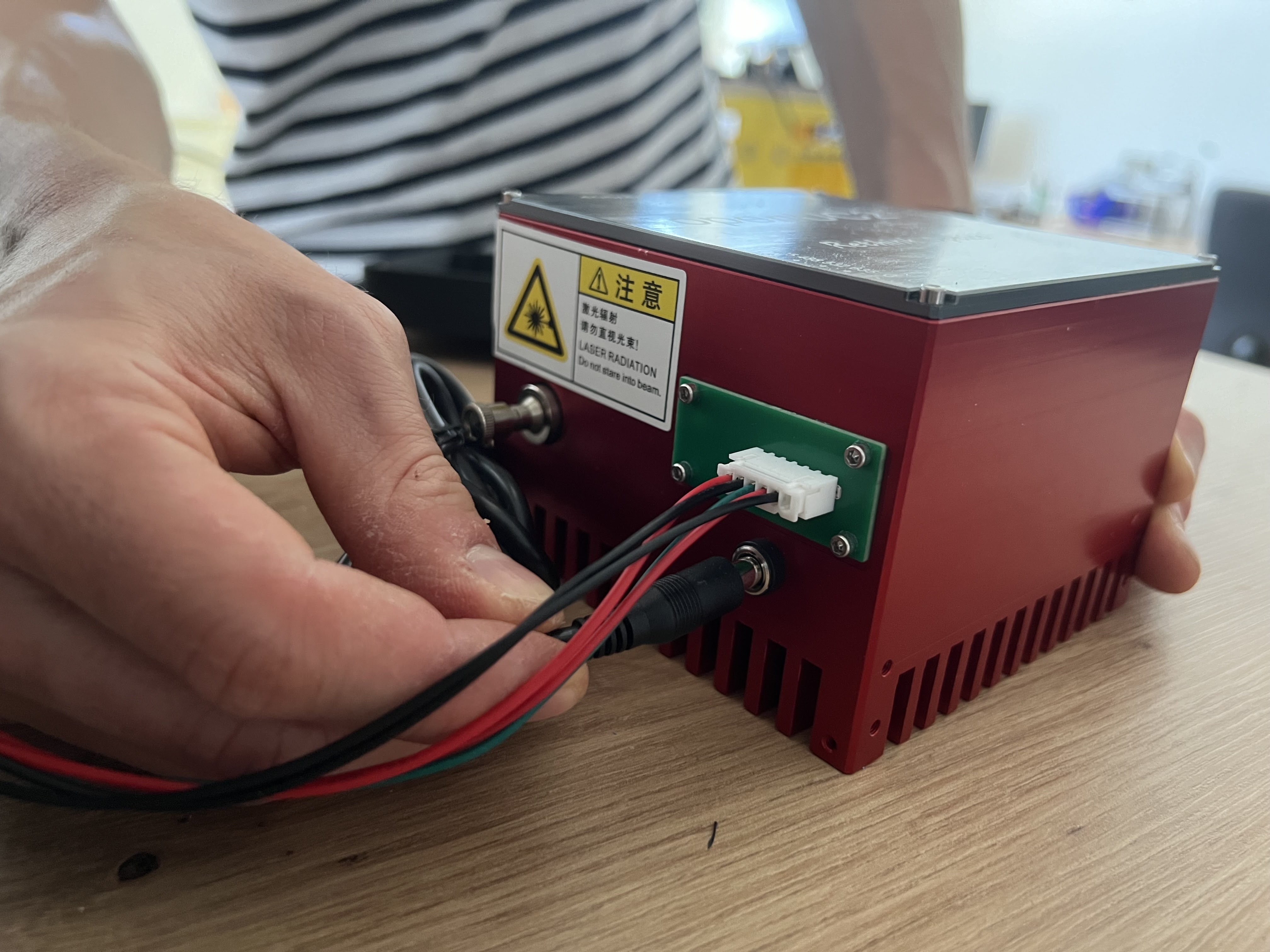 Connect the external 12V power supply for the laser system
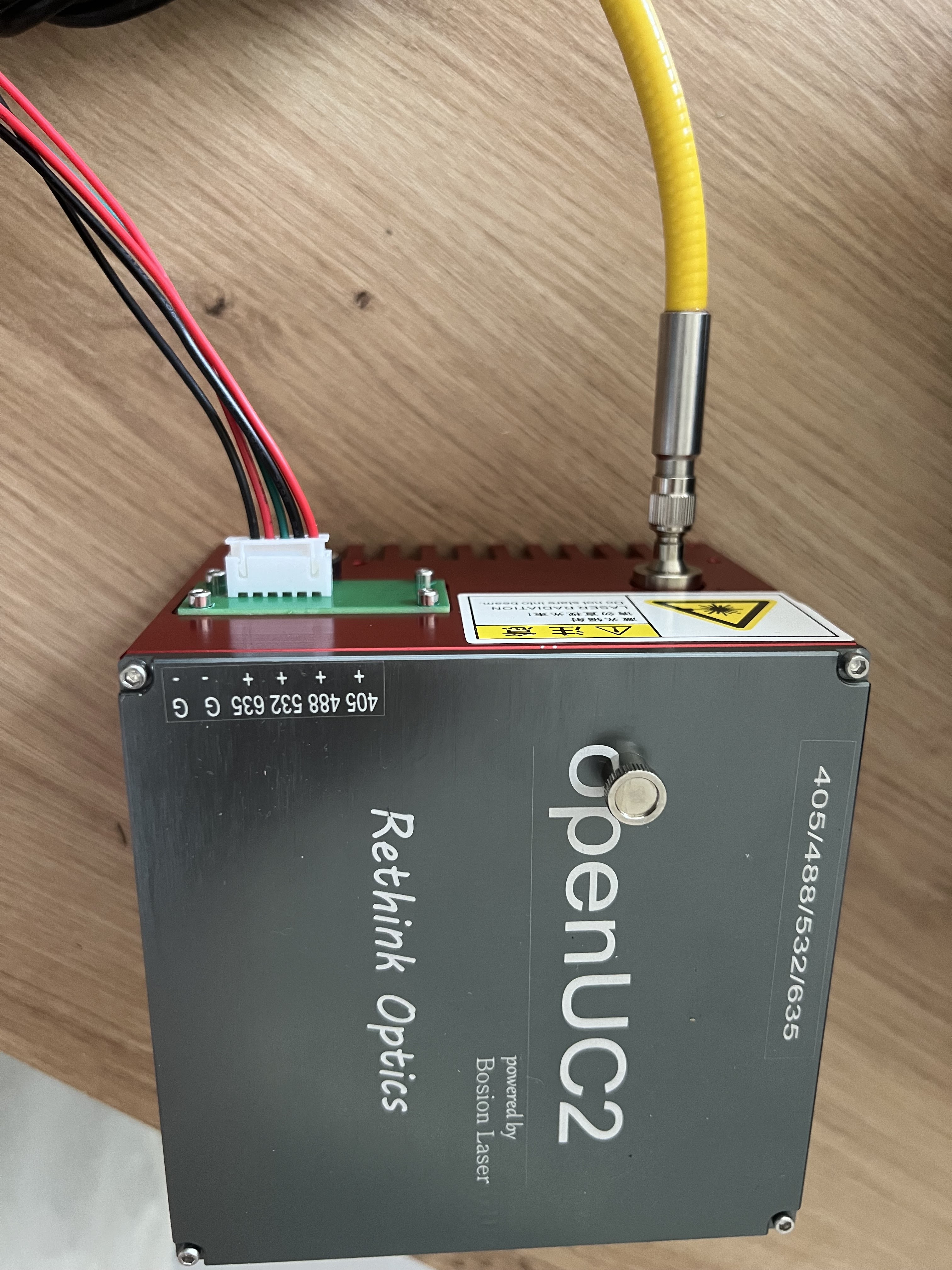 Verify proper wiring configuration on the laser module
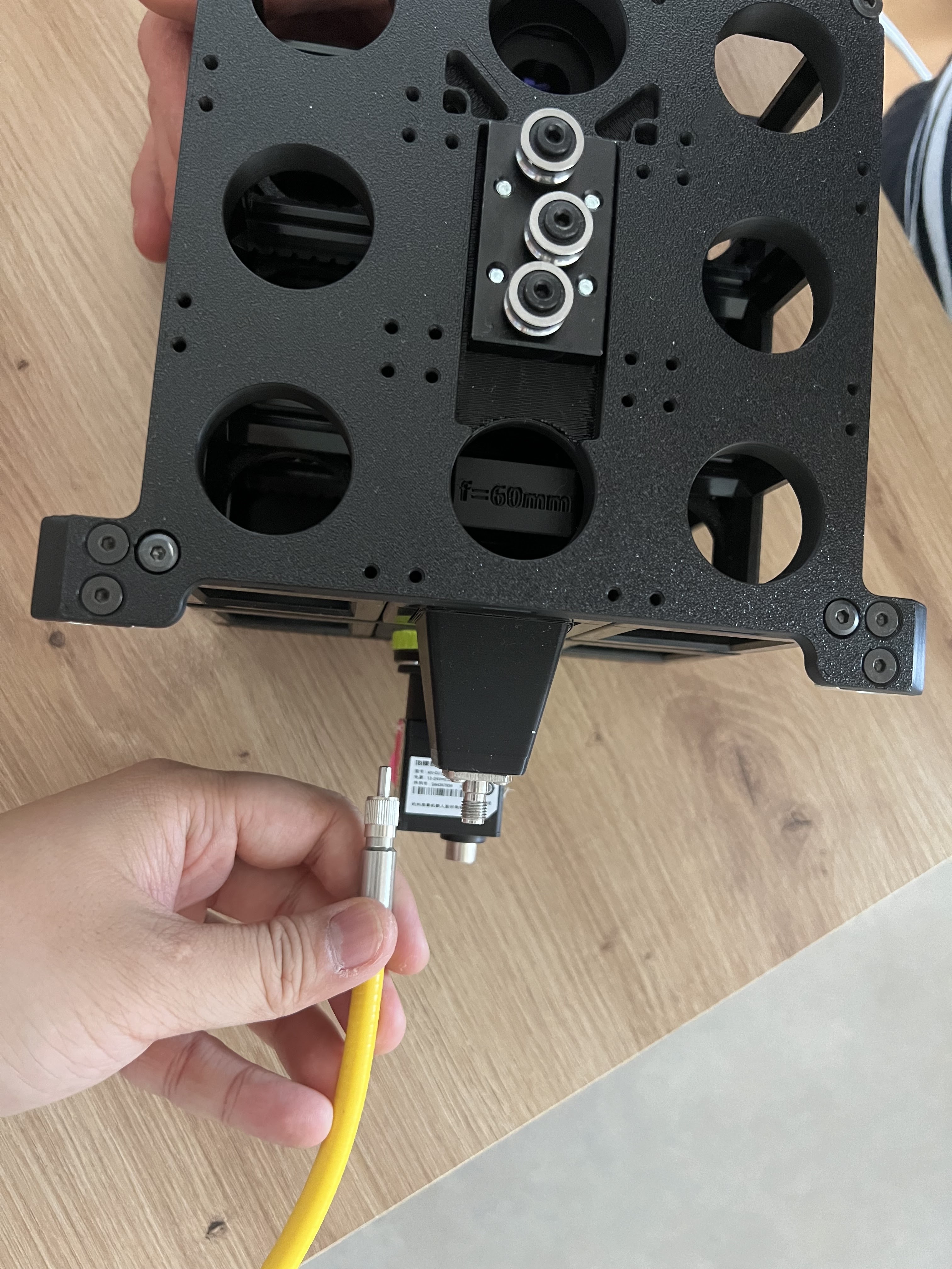
Step 6: Fiber Optic Installation
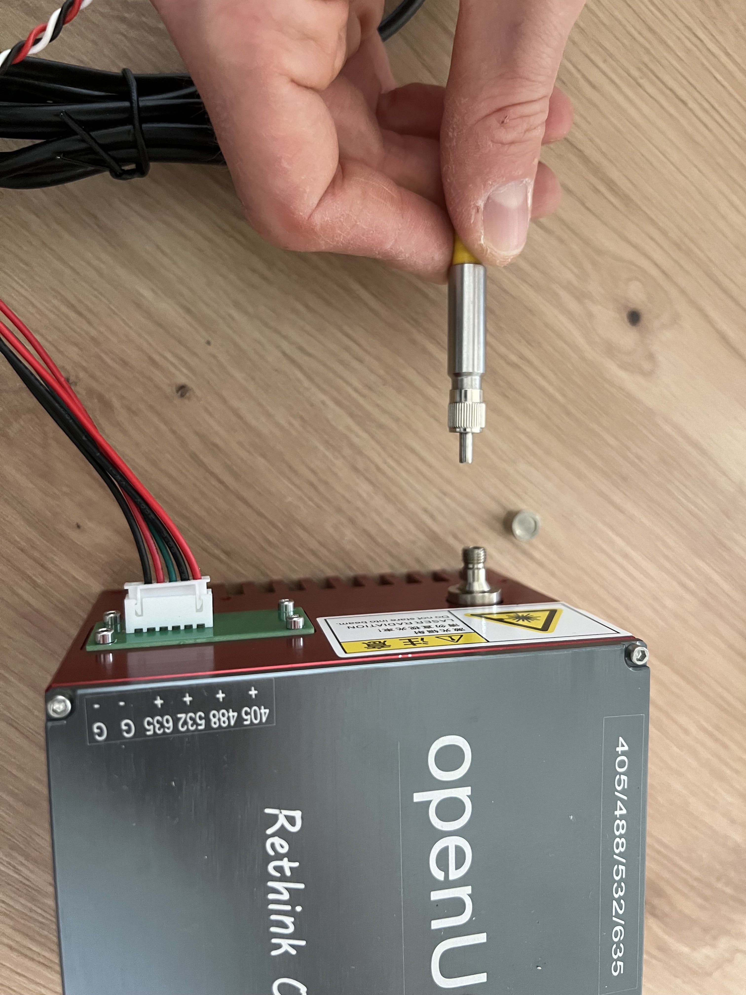 Insert the fiber optic cable into the screw terminal fiber mount
 Carefully remove the protective cap and insert the fiber into the ferrule. Secure with the fiber holder nut.
⚠️ FIBER SAFETY: Never touch the fiber end face as this may damage the core and degrade light transmission.
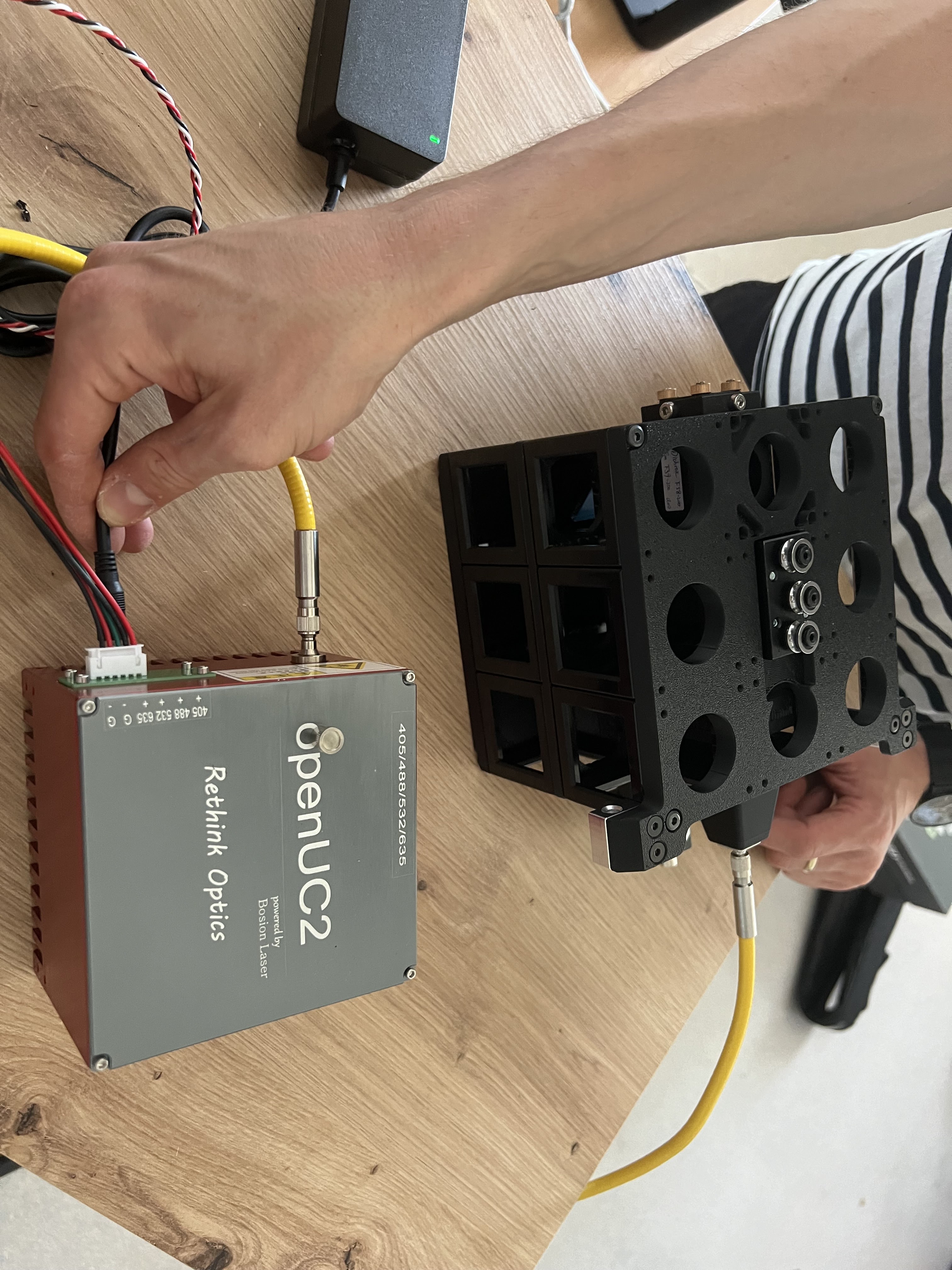 Completed laser installation (configuration may vary depending on internal vs. external laser setup)
Dealing with the Sample calibration target
For information about using the sample calibration target, see the Operation Manual section on calibration procedures.
Software Installation and Configuration
Work In Progress: This is for the case if you want to install imswotch locally..
Step 1: System Software Installation
Driver Installation:
- Install camera drivers
- Install motor controller drivers
- Install communication interface drivers
- Verify device manager shows all devices
Control Software Installation:
- Download latest ImSwitch software
- Install UC2-REST API components
- Configure system parameters
- Load device configuration files
Step 2: Initial Configuration
Hardware Configuration:
- Define axis orientations and directions
- Set travel limits and home positions
- Configure camera parameters
- Calibrate stage positioning
User Interface Setup:
- Configure display preferences
- Set default acquisition parameters
- Create user profiles
- Configure safety interlocks
Optical Alignment and Calibration
Optical Alignment and Calibration
Proper optical alignment is critical for optimal system performance. The FRAME system requires alignment of multiple optical components to achieve proper imaging quality.
Overview of Alignment Process
The optical alignment involves three main steps:
- Internal Optics Cube Preparation - Align the removable optics cube outside the FRAME
- FRAME Integration - Align the cube's optical axis with the FRAME system
- Final Verification - Test and validate all optical paths
Detailed Alignment Procedures
Complete step-by-step optical alignment procedures are provided in:
📁 Reference Document: config_examples/Optical_Alignment_Procedures.md
This document covers:
- Internal optics cube preparation and Köhler illumination setup
- Mechanical alignment using adjustment screws
- FRAME integration and axis alignment
- LED alignment tool setup and usage
- Position storage and calibration
- Troubleshooting common alignment issues
Quick Alignment Summary
Prepare Internal Cube:
- Remove optical module from FRAME
- Set up external alignment fixture
- Align fluorescence path for Köhler illumination
- Center laser beam exit from objective
FRAME Integration:
- Install LED alignment tool
- Align Y-axis using cube adjustment screws
- Align X-axis using electronic positioning
- Store objective positions in EPROM
Verification:
- Test both transmitted and fluorescence paths
- Verify image quality and uniformity
- Confirm objective switching accuracy
Stage Coordinate System and Calibration
The FRAME uses a well-defined coordinate system for precise positioning. Complete details about the coordinate system, calibration procedures, and reference points are provided in:
📁 Reference Document: config_examples/Coordinate_System_Reference.md
Key Points:
- Origin Position: Corresponds to multiwell plate position A1
- Calibration Point: Center reference at xy = 63.5/46 mm
- Maximum Travel: 127 x 86 mm (suitable for multiwell plates)
- Stage Resolution: 0.3125 μm per step
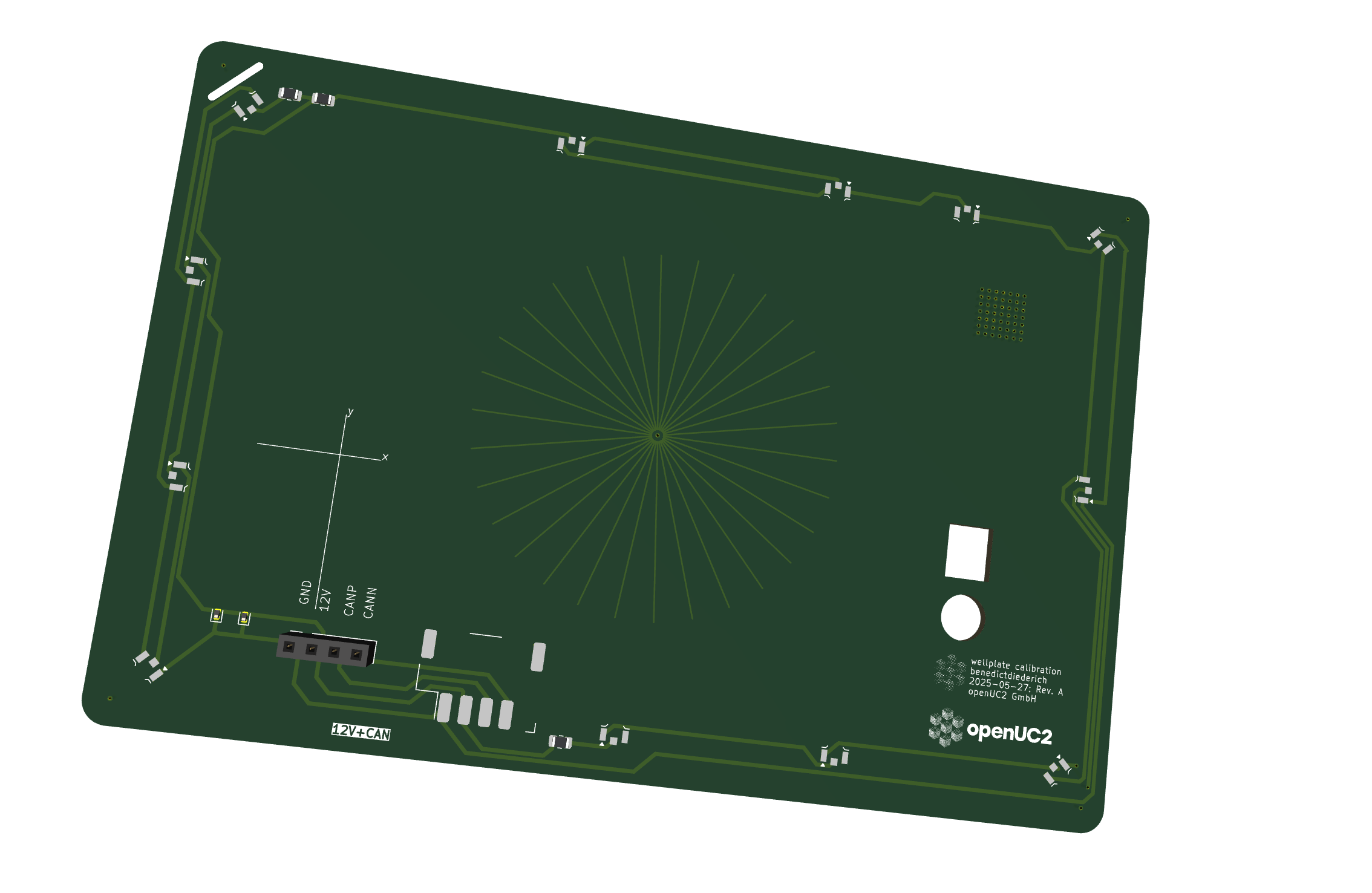 Calibration target with crosshair lines for center positioning
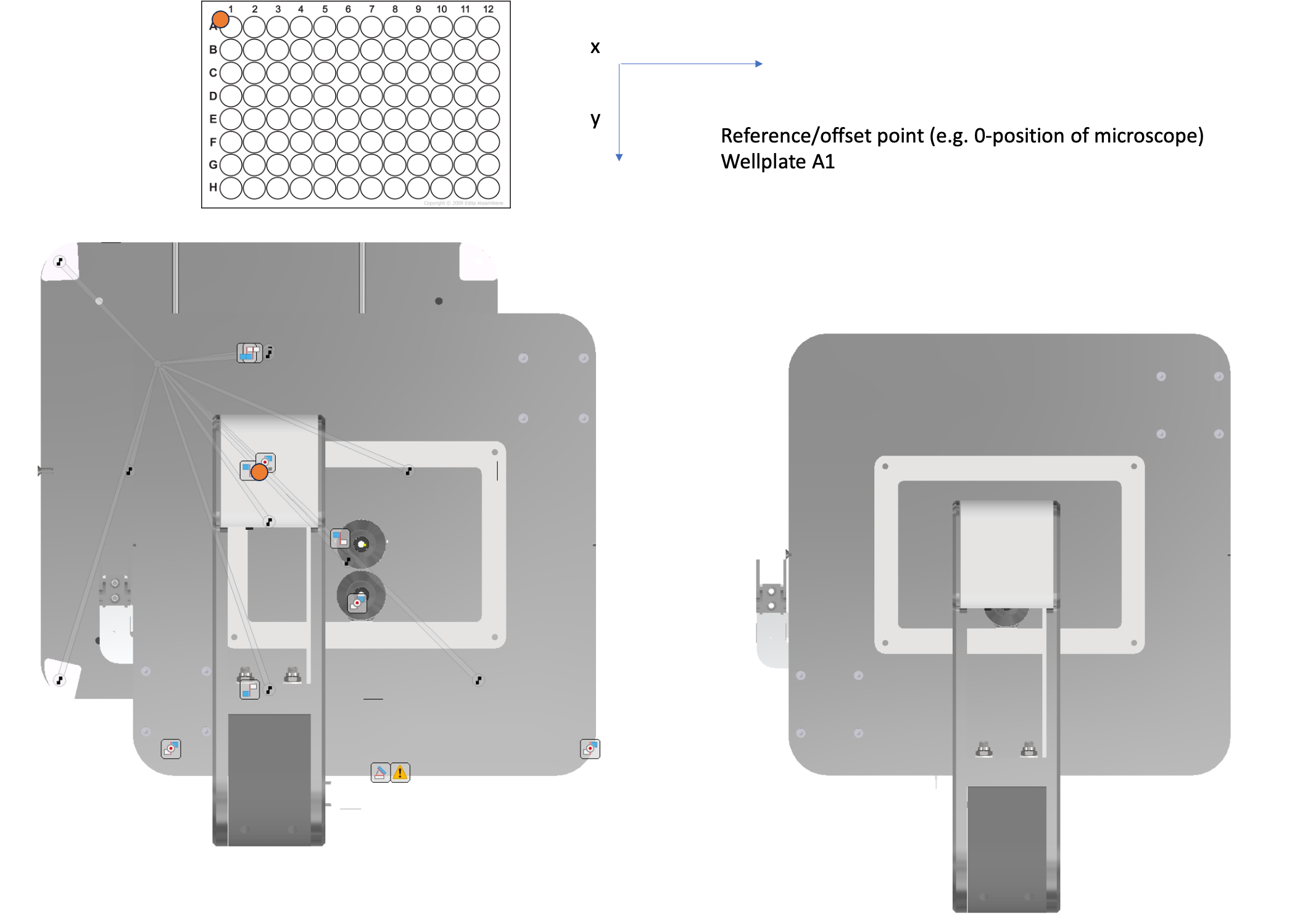 Stage coordinate system showing maximum travel range
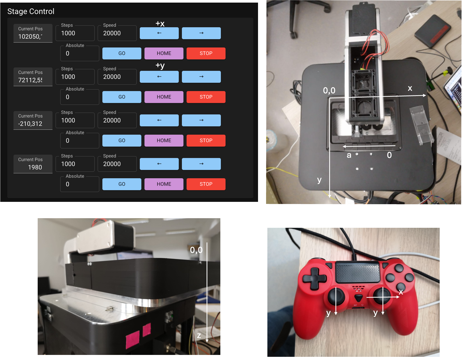 Coordinate system directions and axis orientations
Step 1: Illumination Alignment
Note: This section is under development. Complete procedures will be provided in future updates.
Transmitted Light Setup:
- Center LED illumination for uniform field coverage
- Adjust condenser position for optimal focus (currently only one position - move the LED double cube module along the optical axis so that the brightfield LED is collimated)
- Plexiglass insert will ensure that darkfield/phase contrast rings will pass through
- Verify field uniformity across entire viewing area on the camera (if not homogeneous, the objective slot positions need to be recalibrated)
Step 2: Focus System Calibration
Note: Complete calibration procedures are under development.
- System currently does not have an encoder, so it's wise to home the positions periodically to maintain absolute positioning capabilities
- The system does not track lost steps (e.g., when the stage runs into an endstop and slips steps)
- Execute focus system homing sequence using the home button in the main GUI
- Coming soon: Set appropriate software travel limits (via the
config.json) - Test and verify autofocus functionality (using the button in the main GUI)
Step 3: Camera Alignment
Camera Installation Verification:
- Confirm secure camera mounting to interface
- Verify data cable connections
- Test camera software recognition (MVS Software from HIK Robotics / Galaxy Viewer from Daheng Imaging on your host computer)
- Verify proper image acquisition
Optical Alignment Verification:
- Center camera field of view with optical axis
- Adjust back focal distance for optimal focus
- Verify image sharpness across entire field
- Calibrate pixel size and magnification factors
Step 2: Software Testing
Basic Functions:
- Test image acquisition
- Verify stage control
- Test focus control
- Check illumination control
Advanced Features:
- Test automation sequences
- Verify remote access
- Check data export functions
- Test user interface responsiveness
Customization Options
Customize the Objective Holder
Note: Customization procedures are under development.
The FRAME system supports custom objective holders for specialized applications. Contact support for custom configurations.
Customize the Optical Layers
Note: Layer customization procedures are under development.
The modular cube system allows for custom optical configurations. Detailed procedures for creating custom optical layers will be provided in future documentation updates.
In a nutshell: the different layers of the FRAME can be constructed freely upon users needs. The current version has a 3x3x2 inner cube-array, but it can be adjusted to be longer in the Y direction (e.g. 3x5xN) and in the Z-direction by stacking additional layers and increasing outer pillars' height. The below layers demonstrate how a brightfield imaging setup with a simple folding mirror, a tube lens and a camera can be constructed. Additionally we have a fluorescence layer with a fiber holder, the optics to shape the beam and the kinematic dichroic to focus it in the back focal plane from the imaging objective.
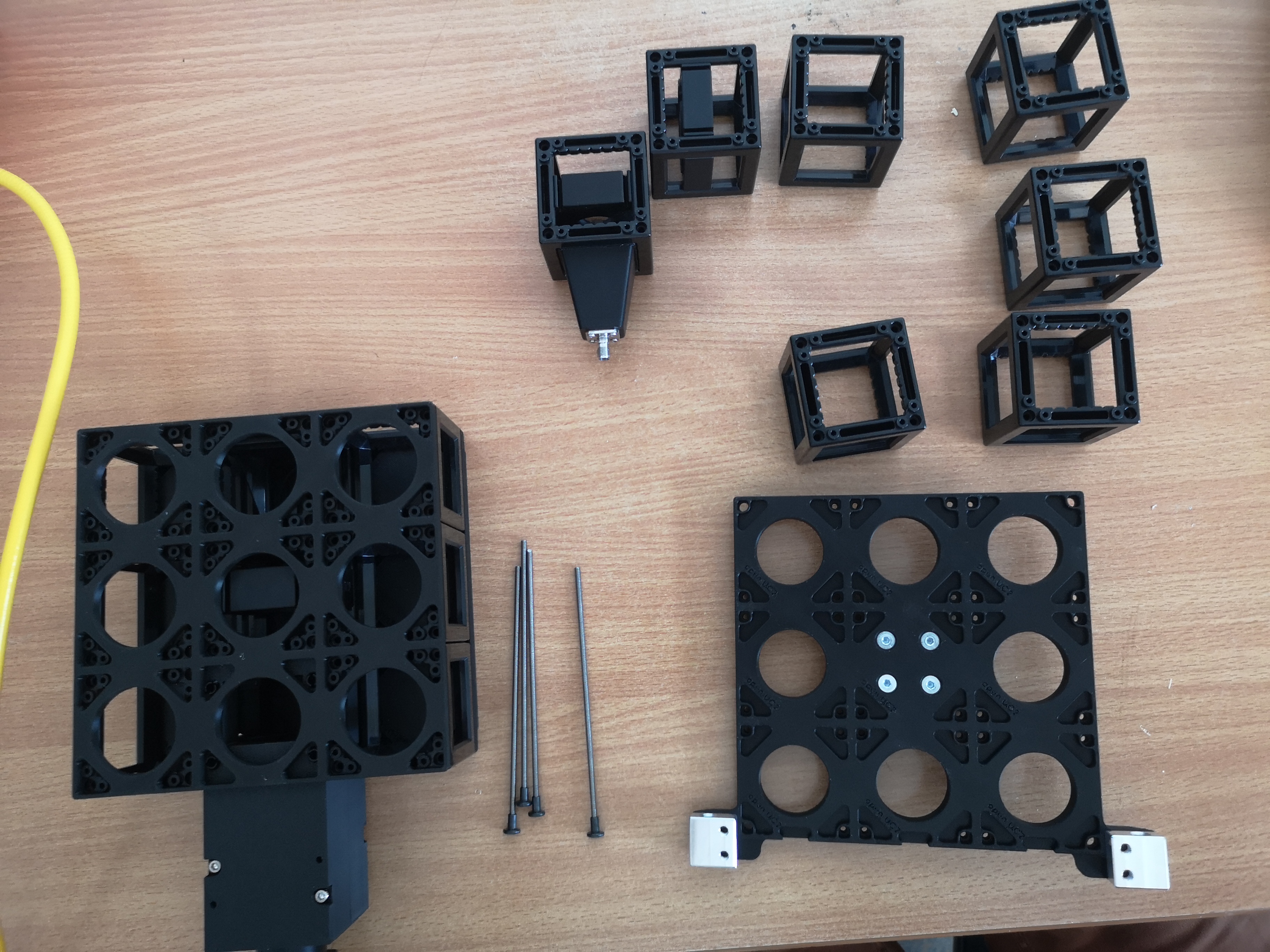 All necessary components - except mirror dicroic mirror of fluroescence layer
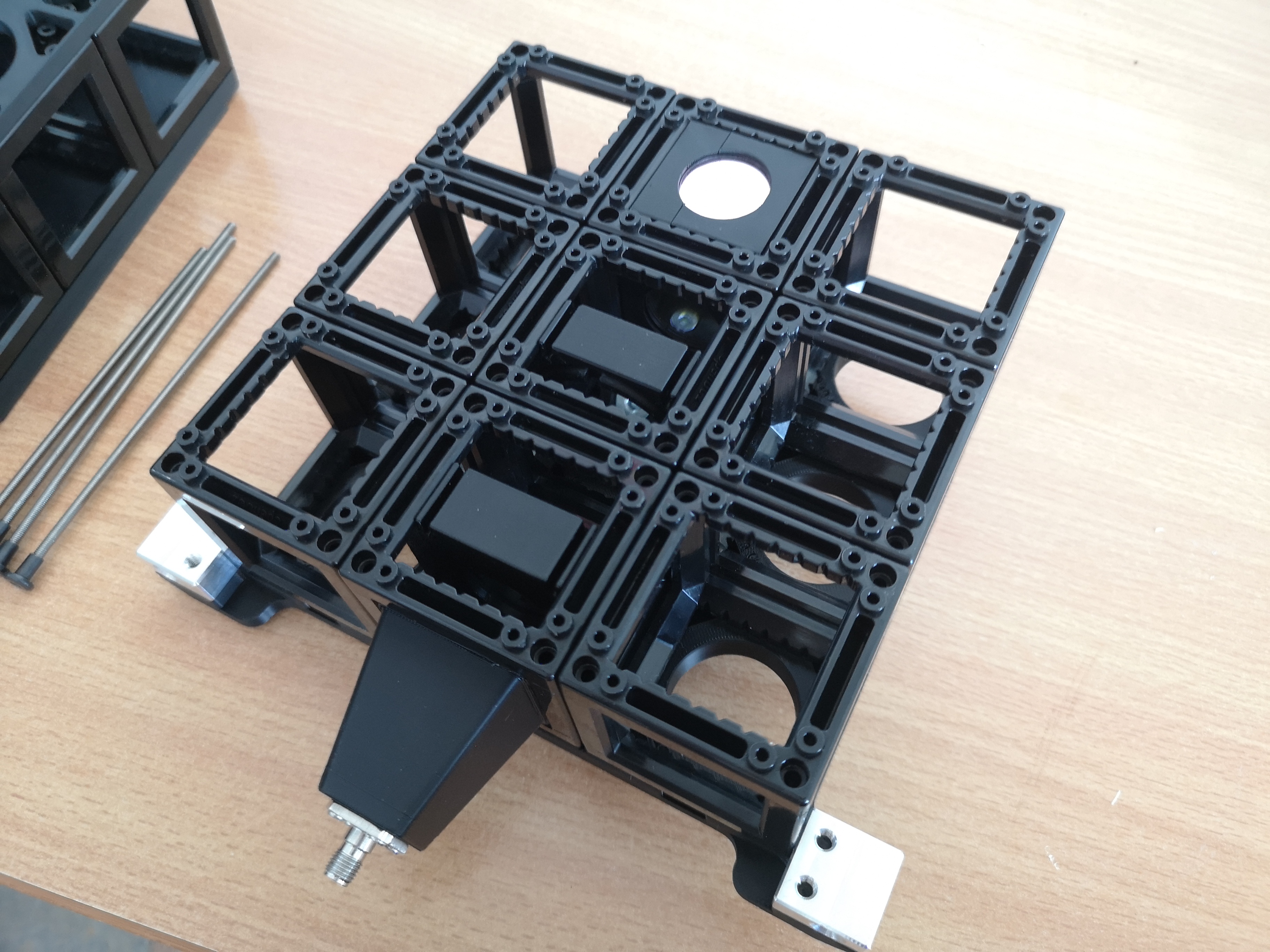 Constructing the Fluorescence Layer on top of the Brightfield layer to build a 3x3x2 cube-array
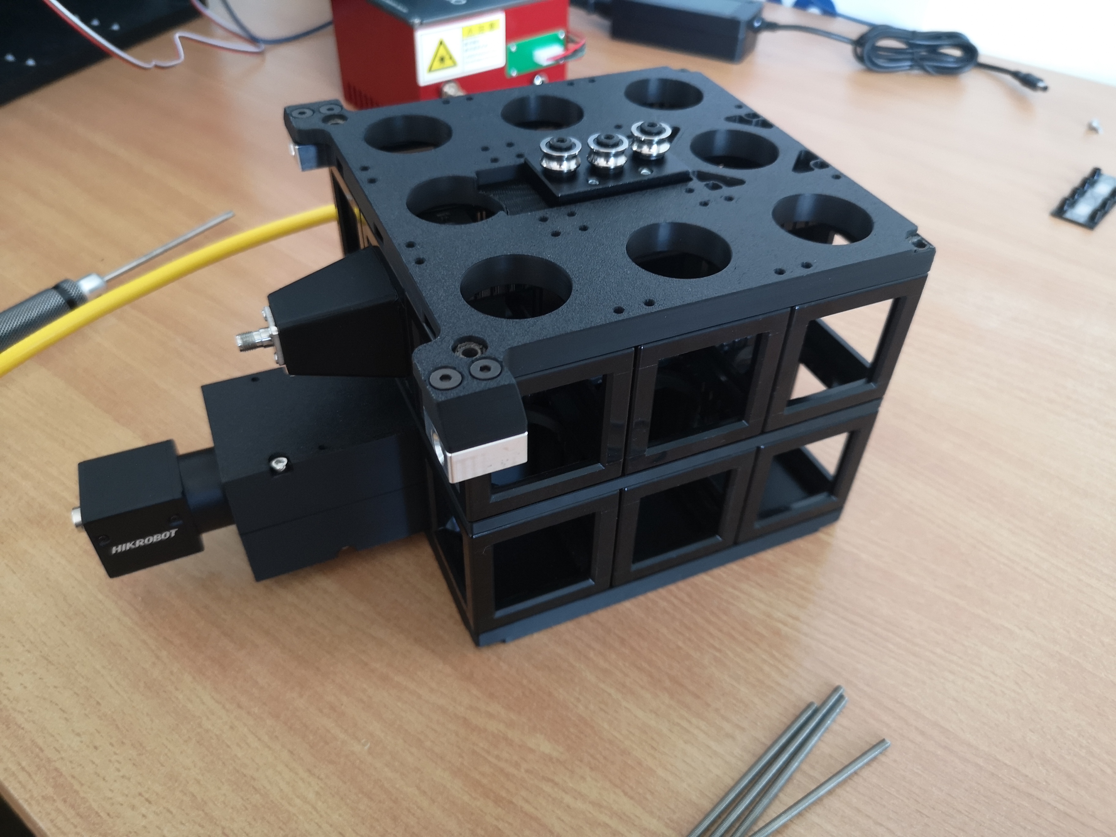 Adding Top Plate on top of the cube-array
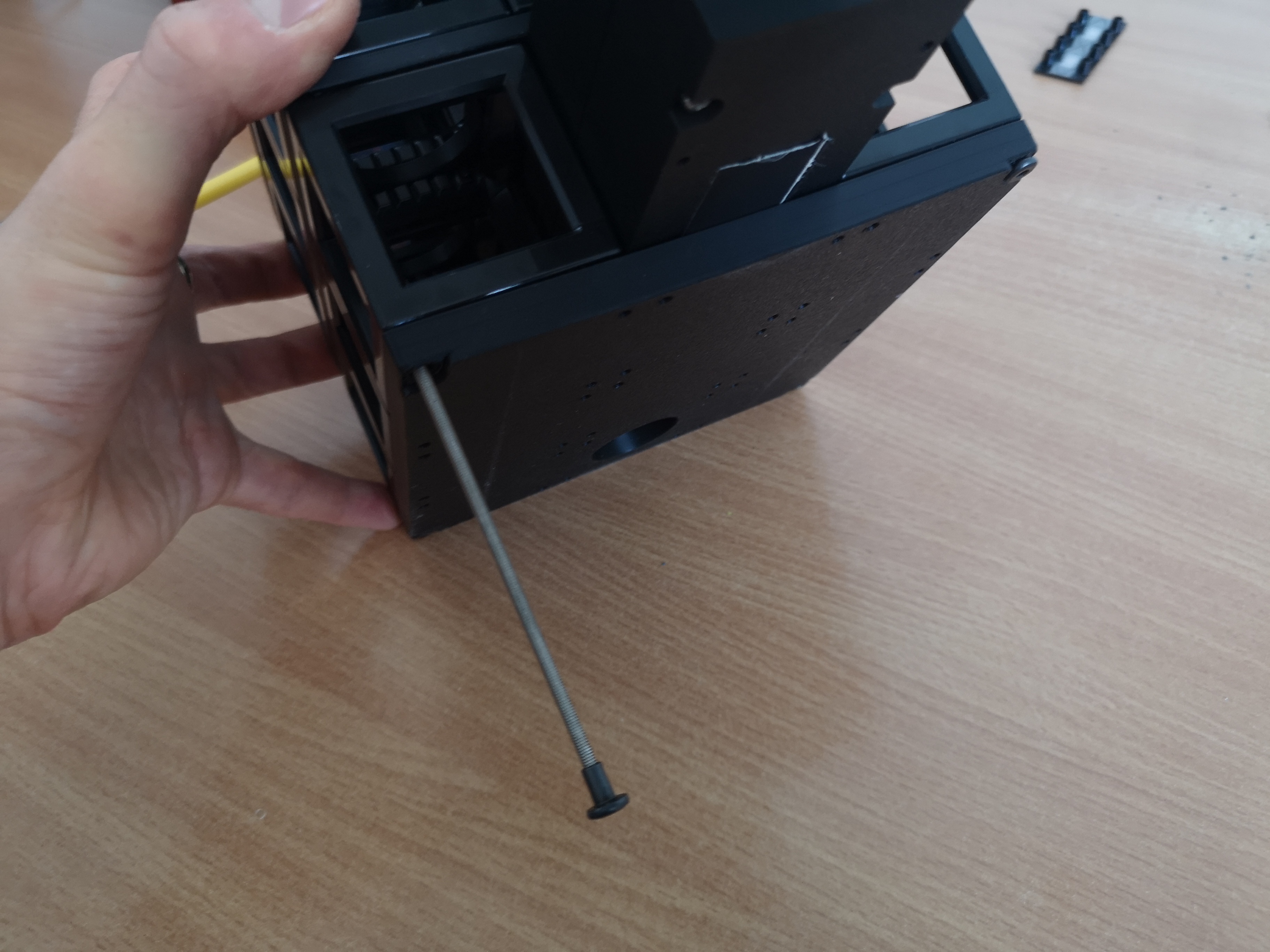 Locking the whole cube-array with extended screws
 Ensuring the screws have a tight fit across all layers
 Ready to use cube-array that can be pre-alligned with optics on top
 Insert pre-alligned 3x3x2 cube-array into the FRAME
Troubleshooting Installation Issues
Common Mechanical Issues
| Problem | Possible Cause | Solution |
|---|---|---|
| Rough stage movement | Misalignment or debris | Check alignment, clean rails |
| Focus drift | Thermal expansion | Allow warm-up time, check mounting |
| Vibration | Unstable surface | Improve vibration isolation |
Common Electrical Issues
| Problem | Possible Cause | Solution |
|---|---|---|
| No power to modules | Fuse blown or wiring error | Check fuses and connections of CAN bus cables |
| Communication errors | CAN-BUS termination | Verify termination resistors (should be activated on HAT) |
| Motor not responding | Driver configuration | Check driver settings or reflash and reconfigure via youseetoo.github.io |
Common Software Issues
| Problem | Possible Cause | Solution |
|---|---|---|
| Device not recognized | Driver not installed | Reinstall drivers |
| Communication timeout | Network configuration | Check IP settings |
| Image acquisition fails | Camera not configured | Verify camera settings |
Continue to Operation Manual for detailed operating procedures.