U.C.STORM
Overview: Fluorescence microscopy is pivotal in life sciences. However, the high cost and complexity of advanced equipment limit its widespread adoption. While open-source scientific hardware offers promising solutions, they often compromise on image quality. To bridge this gap, we introduce the UC2 microscopy toolbox.
Key Features:
- Cost-Effective & High-Quality: Integrates affordable components with state-of-the-art electronics and software for top-notch fluorescence microscopy.
- Versatile Imaging: Achieves high-resolution fluorescence imaging for both fixed and live samples. Enables long-term live-cell imaging when placed in an incubator.
- Advanced Imaging Capabilities: Attains single molecule sensitivity, supports single particle tracking, and SMLM super-resolution microscopy experiments within cells.
- Open-Source Software: Delivers high-quality scientific data generation for both novices and experts at a fraction of commercial system costs.
Impact & Use Cases: Ideal for laboratories with budget constraints, this cost-effective solution matches the capabilities of pricier commercial systems. Moreover, its affordability and ease of use make it an excellent teaching tool for students.
This repository will help you to build a widefield fluorescence microscope and show you how to upgrade it to perform advanced microscopy methods, such as (d)STORM.
Cite this article
You can find the article currently as a biorxiv Preprint:
An open-source, high resolution, automated fluorescence microscope
Ando C. Zehrer, Ana Martin-Villalba, Benedict Diederich, Helge Ewers
bioRxiv 2023.05.31.542706; doi: https://doi.org/10.1101/2023.05.31.542706
How does it look like?
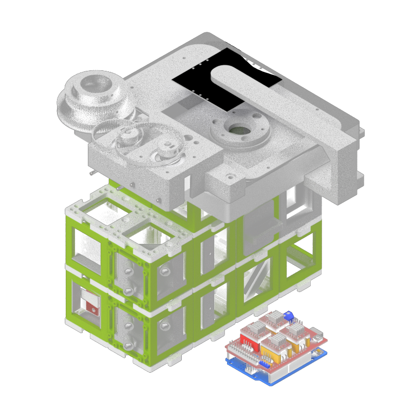
3D View
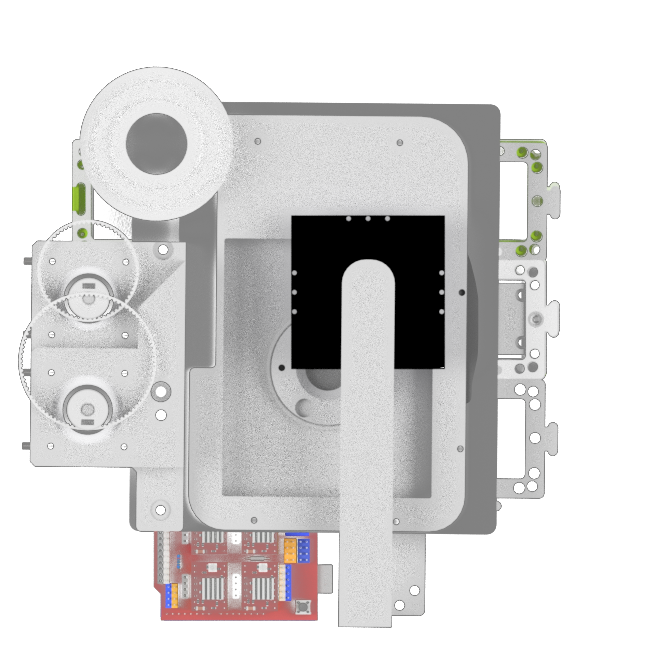
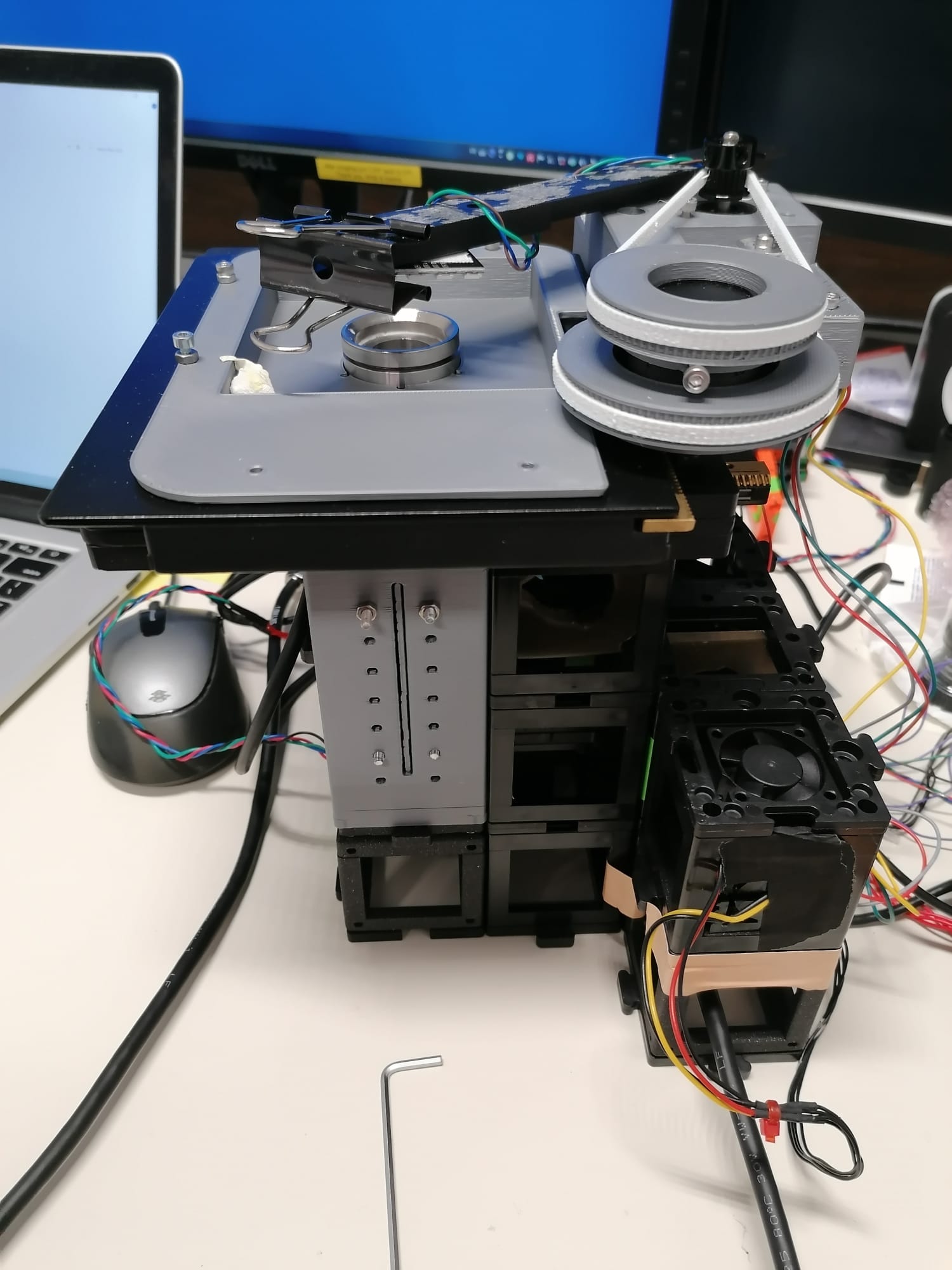
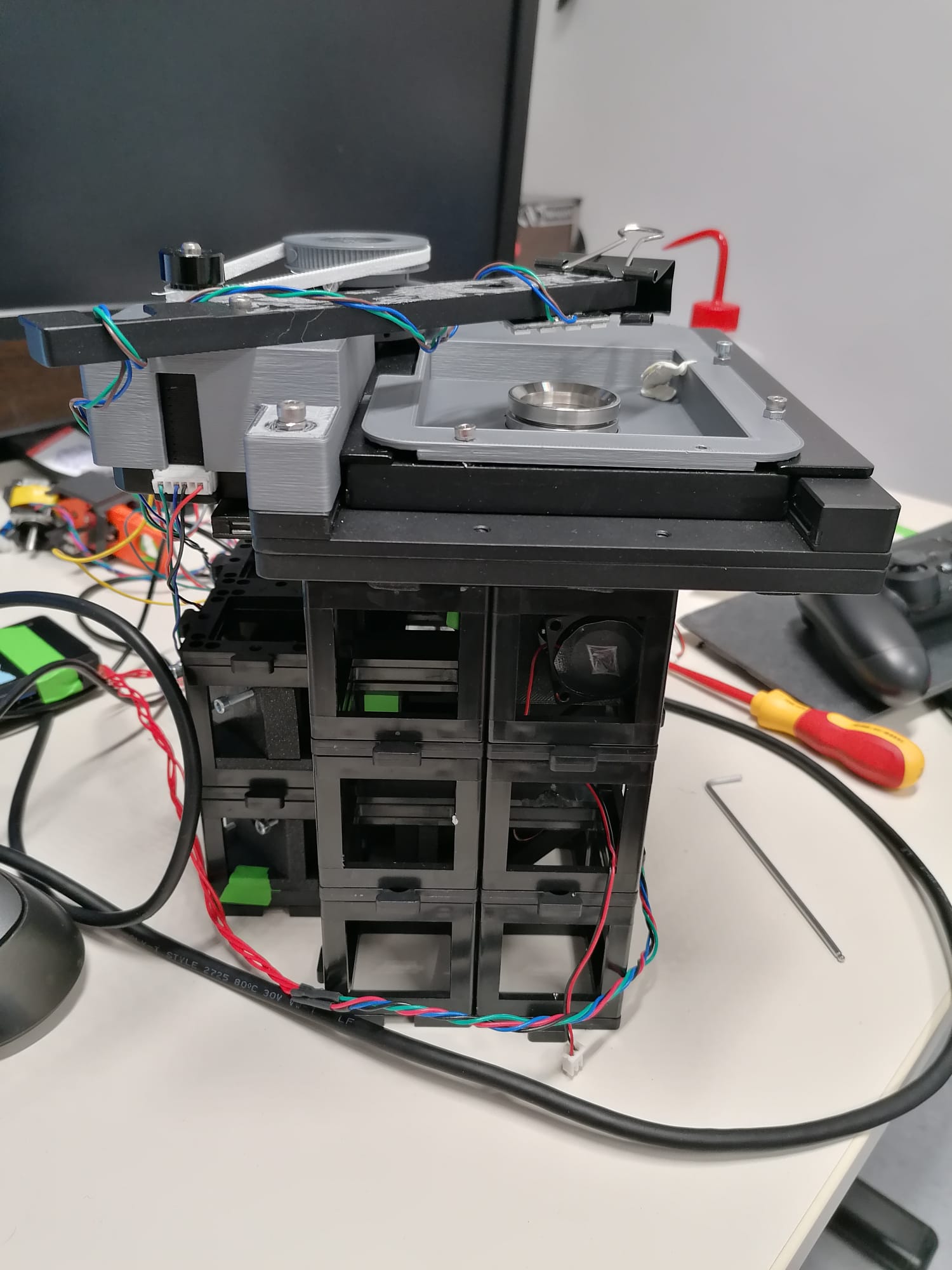
Top View
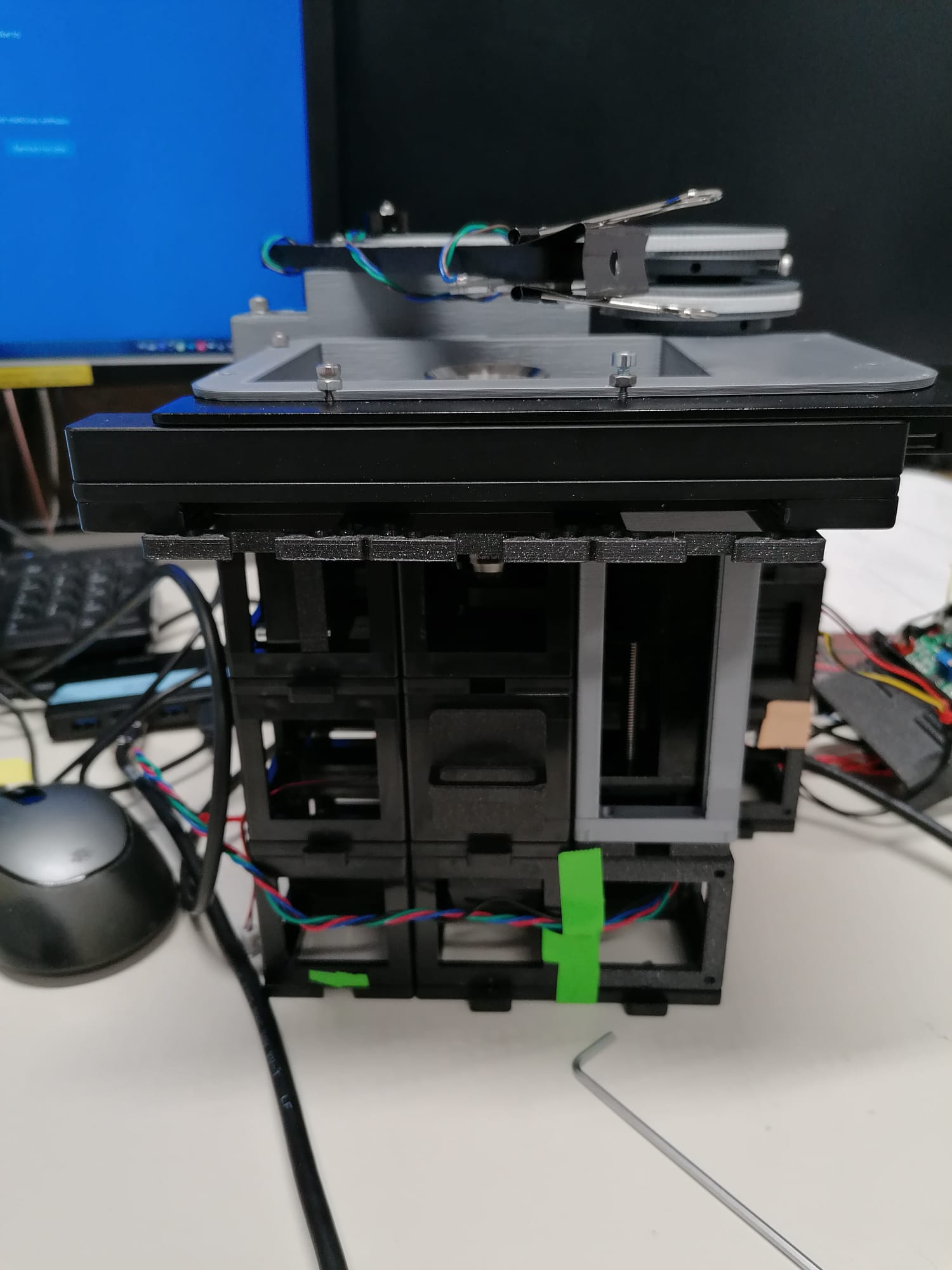
Side View
Features:
- Single-channel fluorescence imaging
- Bright-field imaging
- XYZ motorized automated microscopy
- LED Matrix for quantitative imaging
- Steering fully integrated into ImSwitch
Assembly
Certainly! The instructions you provided seem like a comprehensive guide to building a single molecule localization microscope using the modular optical system UC2. Below, I've expanded on a few aspects to ensure that the steps are clear and more detailed, providing information about some safety precautions, required materials, and additional tips.
Possible to assemble in <2 Minutes
 Obviously, adjusting the lenses and mirrors, as well as adapting self-made 3D printed parts will take some time. However, the framework of the microscope is rapid and simple to build. The cubes can simply be stuck together to get the outlay of the microscope in few minutes. This allows to swiftly exchange modules, make changes and even replace components.
Microscope Building Instructions
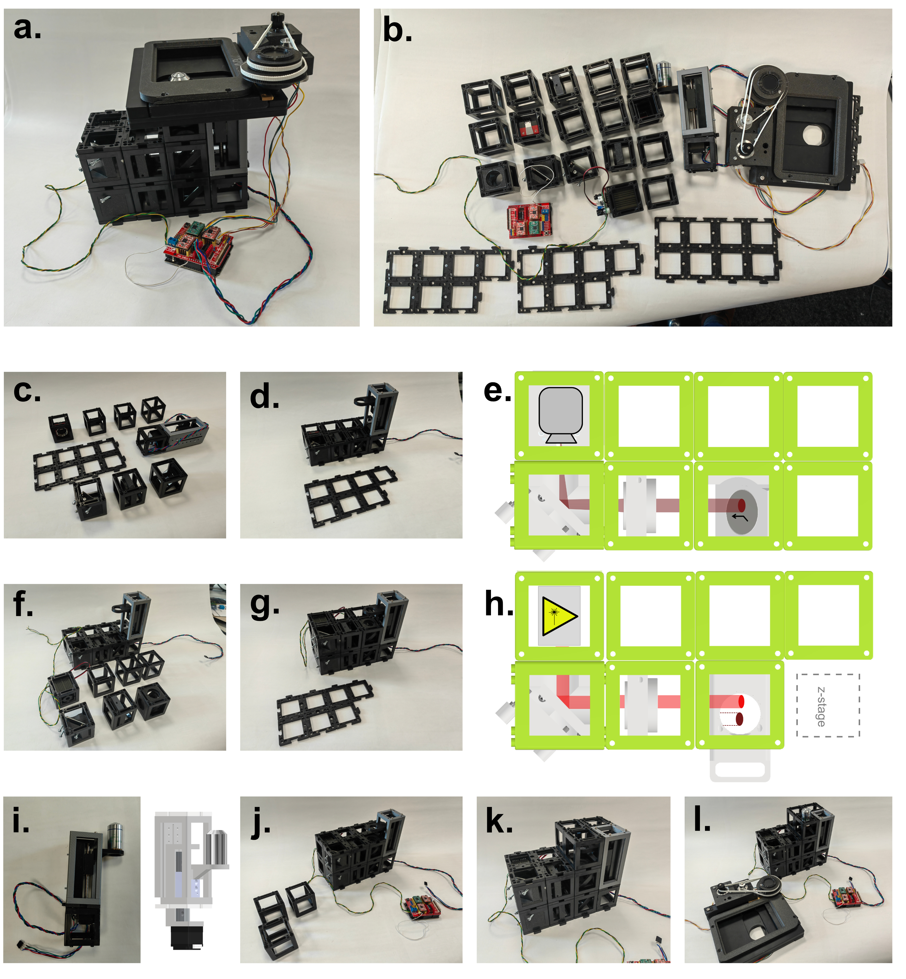 Building the UC2 widefield microscope: a. Photograph of the finished setup. b. Photograph of all single pieces of the dismanteled setup. The bill of materials lists all these components, including CAD files for the 3D printed parts. c. Emission pathway of the microscope. d. Stability increased by using a layer of puzzles below and above the cubes. e. CAD schematic of the emission pathway. f. Excitation pathway of the microscope. g. Excitation layer is also covered by a puzzle layer. h. CAD schematic of the excitation pathway. i. Z-stage photograph and corresponding CAD file. j. Empty cubes work as place-holder between the excitation layer and the microscope stage. k. The objective is screwed into the objective holder. l. By wiring the electronica the stage is ready to use and the microscope functional (see photograph in a.).
0. Introduction and Precautions
Before we begin, make sure that you are working in a well-ventilated area and wearing appropriate safety gear, such as goggles and gloves. Handling lasers requires caution, so follow the manufacturer's guidelines and take necessary safety measures.
Materials and Tools Needed:
- UC2 modular optical system components
- Camera with the compatible mounting system
- Achromatic lens with a suitable mount
- 3D printer (for creating mounts)
- Thorlabs 20mm tube or equivalent
- Laser with adaptable profile
- Convex lenses
- Diffuser (cling foil, etc.)
- Motor-driven translation stage
- 3D printed gears and timing belts
- Commercial XY stage
- 4-well/8-well chambers and circular 18 mm/25 mm cover glass holders
- Alignment tools, such as apertures
- LED for top-light illumination
- Various screws, bolts, and tools for assembly
- Protective gear for handling lasers and other delicate components
1. Detection Layer
The schematic of the layer and the actual composition can be seen in the setup building figure. The camera is positioned within a cube, so that the camera chip is centered. At a distance of 100 mm, the tube lens is positioned on the same optical axis. As a cube is 50 mm broad, an empty cube is placed between the camera and the lens. A 3D printed mount is combined with a Thorlabs 20 mm tube, to which a mounted achromatic lens can be screwed to the tube. The 3D printed mount is thick enough to not tilt while still being movable. The 3D printed mount holding the lens is moved to focus an object on the camera. The mirror can be placed in front of the camera or before the tube lens. The mirror is tiltable along two axes. The emissions from the objective are parallel. The distance can be chosen accordingly to the build. A mirror tilted by 45 degrees reflects the vertical emissions of the sample into the tube lens and subsequently onto the camera.
2. Laser
The laser profile can be tuned to match the application the microscope will be used for. When imaging a Chroma red fluorescent slide, the laser profile can be characterized, and possible variations or inhomogenities can be removed. Without any modification, the laser only illuminates a subset of the field of view. By adding a telescope build, the laser beam is magnified. The modifications proposed in the Illumination section show different illumination patterns, leading to different possible imaging modalities.
Tips:
- Ensure that the diffuser is balanced properly to avoid vibrations that might affect the image quality.
- Calibration of the laser profile according to the application is crucial. Make sure to test different magnifications and diffusions.
3. Excitation Layer
The laser emission can be chosen accordingly. The laser beam is then focused by a lens into the back focal plane of the objective (here after the filter cube in a higher vertical plane). Through a tiltable mirror, the beam can be positioned into the center of the field of view. The filter cube has filters adapted to the laser and the fluorophores used in the experiments. The mount for the laser, the lens, the mirror as well as the filter cube can all be 3D printed. The schematic and actual photograph of the layer within the setup are shown in the setup building figure.
Tips:
- Ensure that all 3D printed components fit perfectly with the rest of the parts.
- The choice of filters must correspond with the laser and the fluorophores used in the experiments.
4. Z Stage
The z stage is a motor driven translation stage. The stage is embedded into a 3D printed case to make the dimensions fit the cube design. A puzzle piece on the top and in the bottom allow to build a stable connection between the stage and the rest of the microscope. A 3D printed objective holder connects the stage to the objective. It is advised to print the objective holder with a high percentage of infill and a stable plastic, as the heavy objective causes strain on the material.
Tips:
- Careful selection of the material for the objective holder is crucial to withstand the weight and strain.
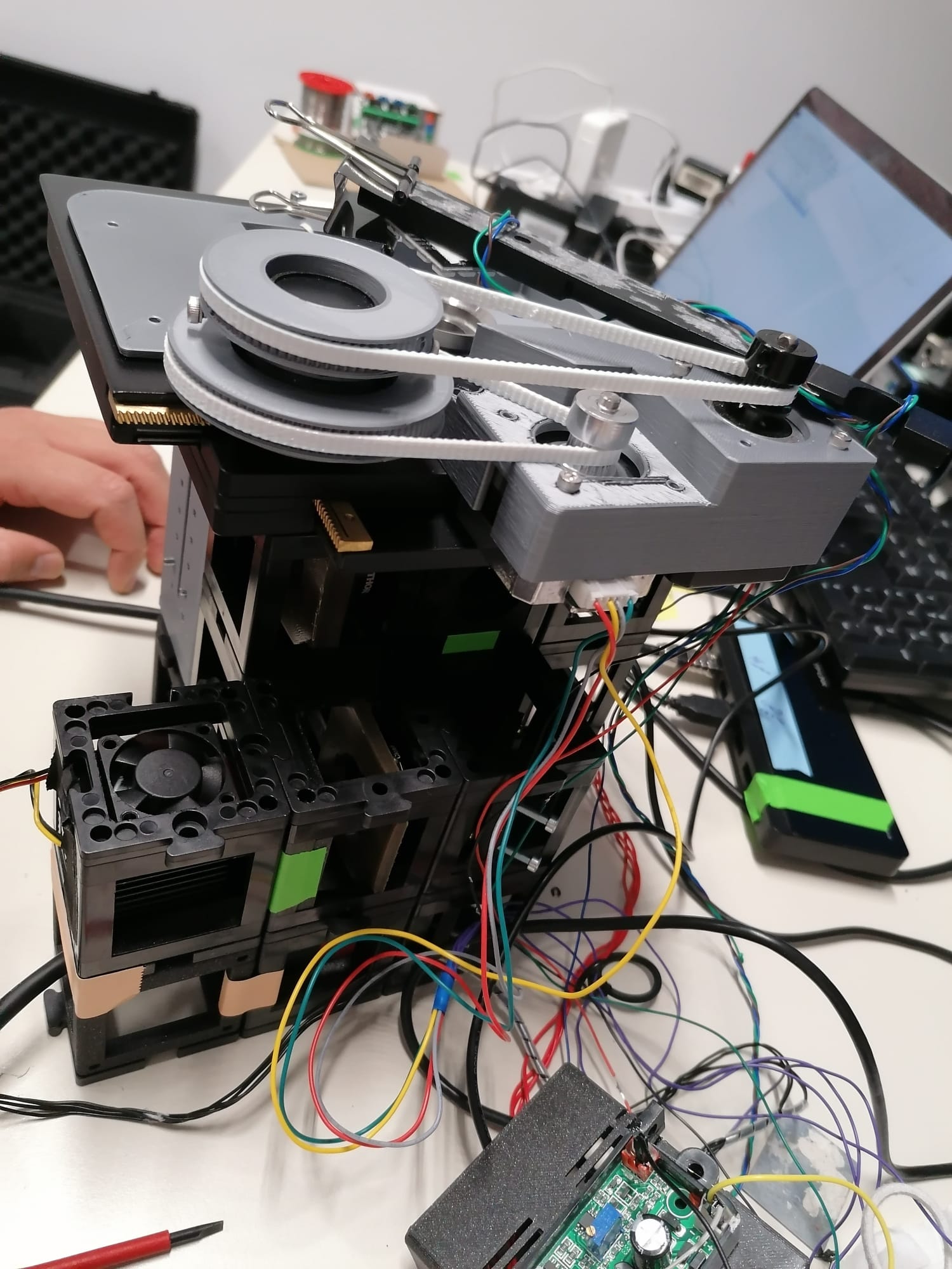
5. XY Stage
The XY stage used in the current build is a commercial solution. The manual translation knobs were equipped with 3D printed gears. In order to motorize the stage, motors which were also equipped with gears transmitted the torque to the stage via timing belts. These were printed with a softer and thus more elastic plastic. The whole stage is attached to the rest of the microscope via a 3D printed plate, working as a replacement for a puzzle layer, with the according perforations where connections to the top layer of cubes was provided. Furthermore, the stage needs a 3D printed insert, to hold the sample. Models for 4-well/8-well chambers and circular 18 mm/25 mm cover glass holders are available. An alternative where the coverglass is directly embedded into the 3D printed sample holder is also provided.
Tips:
- Calibration and testing of the XY stage should be done to ensure smooth and accurate movement.
6. Alignment Procedure
To align the optics, the first step is to position all optics along the optical axis and ensure that they are not tilted. To make this procedure more systematic, the excitation pathway is aligned with an aperture, which is placed between the second lens of the telescope build and the lens focusing the laser in the back focal plane of the objective. While imaging a fluorescent slide, an almost closed aperture is placed to match the maximum of the laser excitation. This allows to know the position of the laser within the sample. The emission pathway is then adjusted to have the aperture in the center of the field of view. This way, the maximal laser intensity spot is in the center of the field of view, which should both theoretically be along the optical axis.
Tips:
- Proper alignment is essential for obtaining accurate results. Take your time and follow systematic procedures.
- Specialized alignment tools and techniques might be needed for precise adjustments.
7. Top Light Illumination
The illumination for bright-field imaging needs to be spatially invariant in relation to the objective. It is important to attach the top-light illumination to the main body of the microscope instead of the XY stage. This is achieved by attaching an LED to a 3D printed arm, connected to the highest puzzle layer, thus decoupled of the possible motions of the XY-stage.
Tips:
- The brightness of the LED should be adjustable to suit various imaging requirements.
- Consider using a diffuser to create more uniform illumination across the sample.
Conclusion
Building a single molecule localization microscope with the modular optical system UC2 is an exciting and challenging project. This guide provides a step-by-step approach to construct the microscope and align its various components. Always remember to follow safety precautions and consult manufacturer's guidelines or a professional if you are unsure about any step.
Feel free to share your progress and ask questions on GitHub or other platforms, as the scientific community can be of great assistance in such projects.
Happy building!
Bill of material
Below you will find all components necessary to build this device
3D printing files
All these files need to be printed. We used a Prusa i3 MK3S using PLA Prusament (Galaxy Black) at layer height 0.15 mm and infill varying between 20-40 %, depending on how much weight rests on the 3D printed part. For applications within the incubator, the use of ABS Prusament is recommended, as the thermal stability is noticeably increasing the setups stability, especially with increased working temperature and humidity. The layer height and the infill can be chosen identically for ABS as for PLA parts.
An in-depth tutorial on how to build the XY-stage can be found here https://github.com/openUC2/
An in-depth tutorial on how to build the Z-stage can be found here https://github.com/openUC2/
| Printed | UC2 | Linear Stage mount | 00_Linear_Stage_NEMA11_Mount.ipt | 1 | $5.00 | 5 |
|---|---|---|---|---|---|---|
| Printed | UC2 | Linear Stage spacer | 00_Linear_Stage_NEMA11_Mount_Lid.ipt | 1 | $1.00 | 1 |
| IM | openUC2 | UC2 Puzzle piece | 10_Base_puzzle_v3.ipt | 26 | $5.00 | 130 |
| Printed | UC2 | UC2 objective Mount linear stage | 20_Cube_Insert_Cube_Z-Stage_NEMA11_china_objectivemount_v3.ipt | 1 | $1.00 | 1 |
| IM | openUC2 | openUC2 IM Cube | 10_Cube_1x1_IM.ipt | 42 | $5.00 | 210 |
| External | 5 mm Neodym Magnets | 00_BallMagnets_5mm_single.ipt | 9 | 0 | ||
| Printed | UC2 | UC2 Insert for Kinematic Mirror Part1 | 20_Cube_Insert_Kinematic_Mirrormount_45_base_part1.ipt | 3 | $5.00 | 15 |
| Printed | UC2 | UC2 Insert for Kinematic Mirror Part2 | 20_Cube_Insert_Kinematic_Mirrormount_45_base_part2.ipt | 3 | $1.00 | 3 |
| Printed | UC2 | Adapter for Nut | 30_Adapter_M3_nut.ipt | 9 | $1.00 | 9 |
| External | Würth | DIN 912 - M3 x 0.5 x 12 x 10.75.ipt | DIN 912 - M3 x 0.5 x 12 x 10.75.ipt | 15 | $1.00 | 15 |
| Printed | UC2 | UC2 Insert for 1 inch Mirror, 45° | 20_Cube_Insert_Kinematic_Mirrormount_45_Thorlabsadapter.ipt | 3 | $5.00 | 15 |
| External | Thorlabs | Thorlabs PF 10-03-P01 | 00_Thorlabs_PF10-03-P01-Step.ipt | 3 | $25.00 | 75 |
| External | Allied Vision Alvium USB 3.1 Kamera 1800 U-158m, 1/2,9", 1,58 MP, C-Mount, monochrom | Varies | 2 | $445.00 | 890 | |
| External | C:\cad\PSP2011Client\Work\139705407318IP01941702.stp | 00_Basler_ace_USB3_C-Mount.ipt | 1 | 0 | ||
| UC2 | 20_Cube_Insert_Cmount_v3.ipt | 1 | $5.00 | 5 | ||
| External | Thorlabs | Thorlabs CP33 | 00_Thorlabs_Cage_CP33_M.ipt | 2 | $20.00 | 40 |
| Printed | UC2 | UC2 Insert for Thorlabs Cage | 20_Cube_Insert_Thorlabs_Pins.ipt | 2 | $5.00 | 10 |
| Printed | UC2 | UC2 Insert for Thorlabs 1inch lens | 20_Cube_Insert_Thorlabs_SM1Tube.ipt | 2 | $5.00 | 10 |
| Thorlabs | Thorlabs AC254-050-A-ML | 00_THORLABS_AC254-050-A-ML-Step.ipt | 2 | $100.00 | 200 | |
| Printed | UC2 | Filtermount | 30_Cube_Insert_Filter_Revolver_Filter_base_single_v3.ipt | 1 | $5.00 | 5 |
| External | Euromex | Euromex Mechanischer 180 x 155 mm Objekttisch mit integriertem 75 x 55 mm X-Y-Kreuztisch und transparenter Glasplatte, NZ.9505 | 00_XYTable_china_75_55mm.ipt | 1 | $200.00 | 200 |
| Printed | Uc2 Insert for Allied Vision Camera | 30_XYTabel_Aliexpress_basplateadapter.ipt | 1 | $7.00 | 7 | |
| Printed | Motormount for XY stge | 30_XYTable_Aliexpress_motormount.ipt | 1 | $7.00 | 7 | |
| Printed | Sample Inset for XY Stage | 30_XYTable_Aliexpress_sampleinsert_round.ipt | 1 | $7.00 | 7 | |
| External | Roboter Bausatz | GT2 Riemenscheibe 16 Zähne 4mm Bohrung für 6mm Zahnriemen | 00_XYTable_pulley.ipt | 2 | $2.00 | 4 |
| Printed | UC2 | Timing Gear Small | 00_XYTable_medium_gear.ipt | 1 | $2.00 | 2 |
| UC2 | Timing Gear Large | 00_XYTable_large_gear.ipt | 1 | $2.00 | 2 | |
| Printed | UC2 | Printed Timing Belt Long | 00_GT2_TimingBelt_flexible_Modular_xytable_large_89tooth.ipt | 1 | $5.00 | 5 |
| Printed | UC2 | Printed Timing Belt Short | 00_GT2_TimingBelt_flexible_Modular_xytable_large_65tooth.ipt | 1 | $5.00 | 5 |
| External | Laserlands.net | 638nm Red Laser Module 500mW Round Dot Focusable TTL 3050 | 00_LASER_640nm.ipt | 1 | $40.00 | 40 |
| Printed | UC2 | holder for LED Array | 40_Cube_XY_Table_Illumination_Arm.ipt | 1 | $5.00 | 5 |
| External | Adafruit | Adafruit 64 LED array (8x8) | 00_LED-ARRAY.ipt | 1 | $20.00 | 20 |
| External | Chroma | Chroma ET655 | 00_Chroma_ET655lp long-pass.ipt | 1 | $250.00 | 250 |
| External | Chroma | Chroma ZET 636 | 00_Chroma ZET635_Excitationfilter.ipt | 1 | $250.00 | 250 |
| External | Chroma | Chroma ZT640 | 00_Chroma_ZT640rdc.ipt | 1 | $250.00 | 250 |
| External | - | Linear Stage 50mm , Nema 12, MGN9h | 1 | 50 | 50 |
Design files
The original design files are in the INVENTOR folder.
Showcase
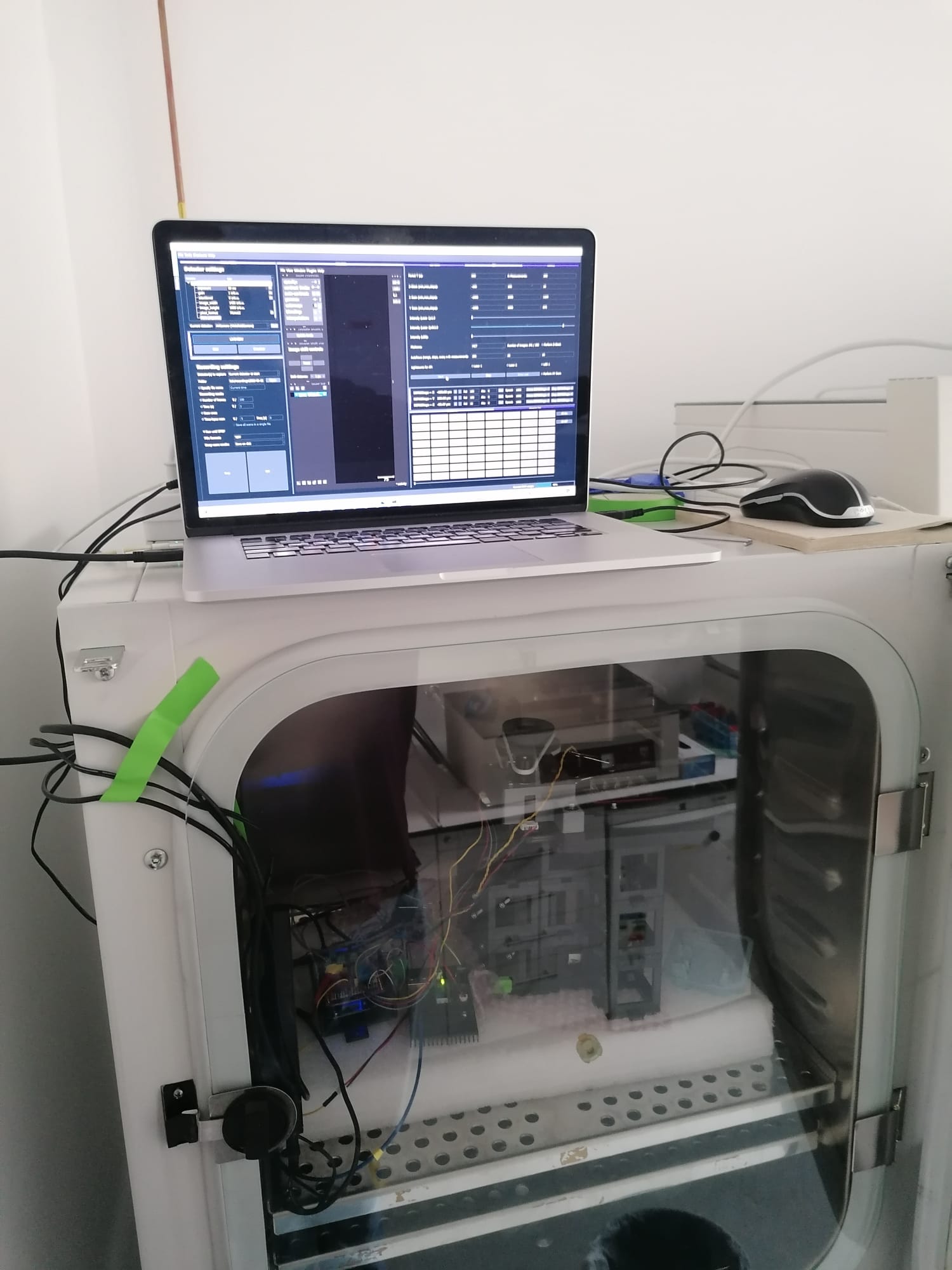
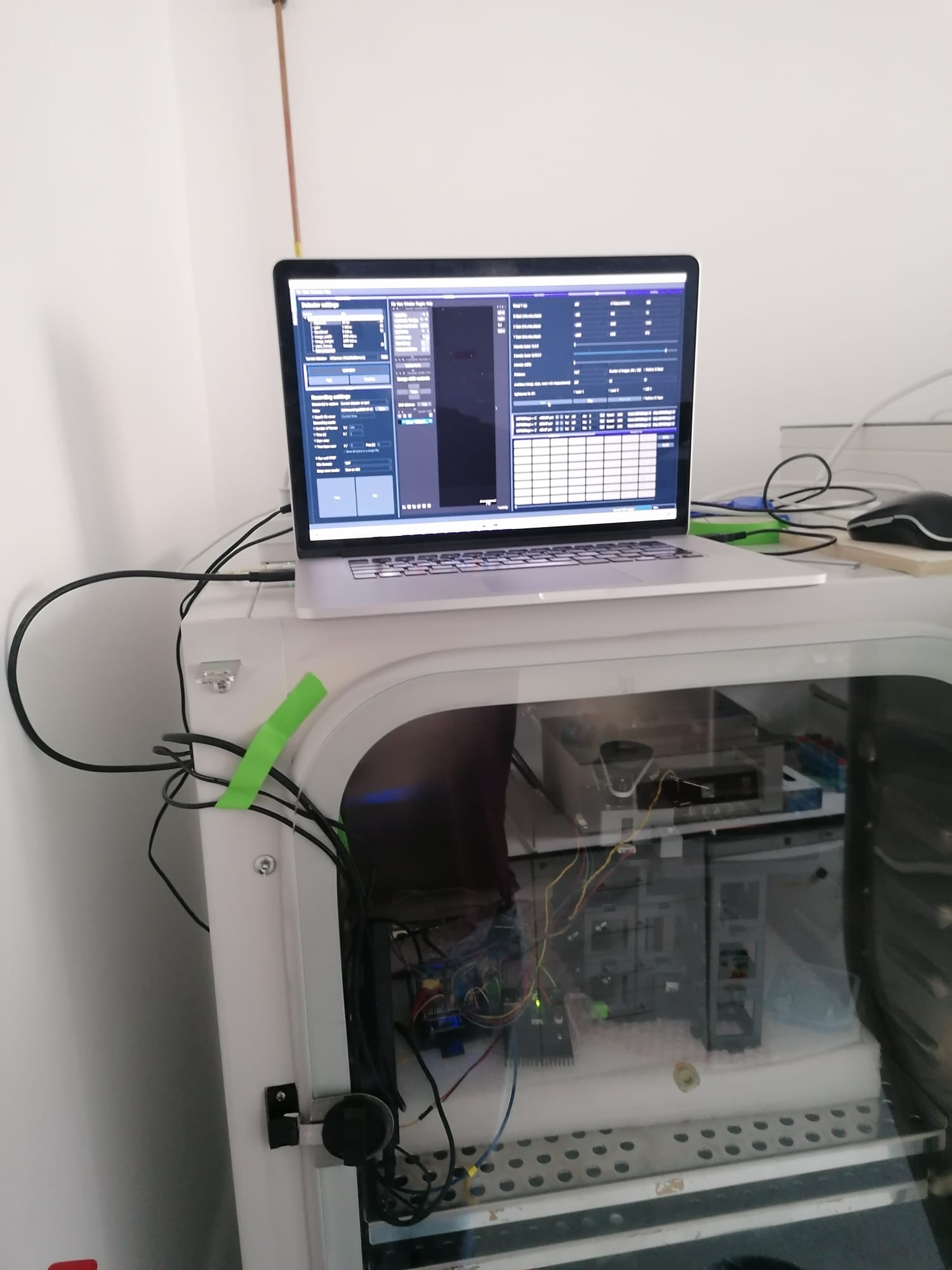
The compact size of the setup and the modular character allow to adapt the setup to any incubator. ImSwitch can be started from any given compute ror laptop. Simple USB cables connect the microscope to the outside (computer) for full control over its functionalities. Here you can see the device in action:
Example of the setup being used within a cell culture incubator for continuous imaging of cells.
Mechanical stability of the setup
See the mechanical stability section of the repository.
Wide-field imaging, Live-cell imaging, Single molecule applications
See the Results section of the repository.
Get Involved
This project is open so that anyone can get involved. You don't even have to learn CAD designing or programming. Find ways you can contribute in CONTRIBUTING
License and Collaboration
This project is open-source and is released under the CERN open hardware license. Our aim is to make the kits commercially available. We encourage everyone who is using our Toolbox to share their results and ideas, so that the Toolbox keeps improving. It should serve as a easy-to-use and easy-to-access general purpose building block solution for the area of STEAM education. All the design files are generally for free, but we would like to hear from you how is it going.
You're free to fork the project and enhance it. If you have any suggestions to improve it or add any additional functions make a pull-request or file an issue.
Please find the type of licenses here
REMARK: All files have been designed using Autodesk Inventor 2019 (EDUCATION)
Collaborating
If you find this project useful, please like this repository, follow us on Twitter and cite the webpage or the publication! :-)