Tutorial: Building an ODMR (Optically Detected Magnetic Resonance) Setup
In this workshop, we will construct an ODMR (Optically Detected Magnetic Resonance) system using the UC2 modular microscope toolbox and NV (Nitrogen-Vacancy) diamonds. ODMR is a quantum sensing technique that allows us to measure magnetic fields by observing changes in fluorescence from quantum systems. This experiment introduces students to quantum mechanics, spin physics, and modern sensing applications at room temperature.
 3D rendering of openUC2 ODMR setup
Theory of Operation
The ODMR setup operates by using laser light to excite nitrogen-vacancy (NV) centers in diamond crystals and detecting their fluorescence. When microwave radiation at the resonant frequency (approximately 2.87 GHz) is applied, it causes transitions between quantum spin states, resulting in a measurable decrease in fluorescence intensity. This effect forms the basis for sensitive magnetic field measurements.
The system works as a quantum magnetometer by monitoring the fluorescence output while sweeping microwave frequencies. At resonance, fewer photons are emitted due to quantum spin transitions, creating characteristic dips in the fluorescence signal. External magnetic fields shift these resonance frequencies, allowing precise magnetic field measurements.
Theoretical Background
Quantum Spin and NV Centers
Nitrogen-vacancy (NV) centers are point defects in diamond consisting of a nitrogen atom adjacent to a vacant lattice site. These quantum systems have unique properties that make them ideal for sensing applications:
Electronic Structure and Spin States
- NV centers possess a spin-1 ground state with three possible spin projections: ms = -1, 0, +1
- The ms = 0 state is separated from ms = ±1 states by approximately 2.87 GHz
- Optical excitation and relaxation cycles depend on the spin state
Optically Detected Magnetic Resonance Principle
The ODMR effect relies on spin-dependent fluorescence:
- Optical Pumping: Green laser light (532 nm) preferentially initializes NV centers into the ms = 0 spin state
- Microwave Manipulation: Resonant microwaves drive transitions between spin states
- Optical Readout: Red fluorescence intensity depends on the spin state population
- Magnetic Sensitivity: External magnetic fields shift resonance frequencies via the Zeeman effect
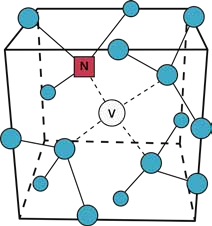
NV Center in a diamond lattice
The Zeeman Effect and Magnetic Field Sensing
When an external magnetic field is applied, the energy levels of the NV center split according to:
- E = D + γmsBz (where D ≈ 2.87 GHz, γ is the gyromagnetic ratio, and Bz is the magnetic field)
- This splitting creates two resonance peaks separated by 2γBz
- Measuring the frequency separation directly gives the magnetic field strength
Quantum Coherence and Sensitivity
NV centers maintain quantum coherence at room temperature, enabling:
- Single-spin sensitivity: Individual NV centers can be addressed optically
- Long coherence times: Quantum states remain stable for microseconds
- High spatial resolution: Nanoscale magnetic field mapping
- Broad temperature range: Operation from cryogenic to elevated temperatures
Confocal Microscopy Setup
The optical configuration follows confocal microscopy principles:
- Excitation path: Laser light is focused onto NV centers using a converging lens
- Collection path: Fluorescence is collected through the same lens (confocal configuration)
- Spectral separation: Dichroic beam splitter separates excitation and fluorescence wavelengths
- Optical Detection: A lens is collecting the emitted light and focusses it on a photodiode (Adafruit) to readout the signal
Modern Applications and Significance
ODMR with NV centers represents a leading quantum sensing technology with applications in:
- Biomedical imaging: Mapping magnetic fields in living cells and tissues
- Materials science: Studying magnetic domains and spin transport
- Fundamental physics: Testing quantum mechanics and measuring fundamental constants
- Quantum information: Building blocks for quantum computers and networks
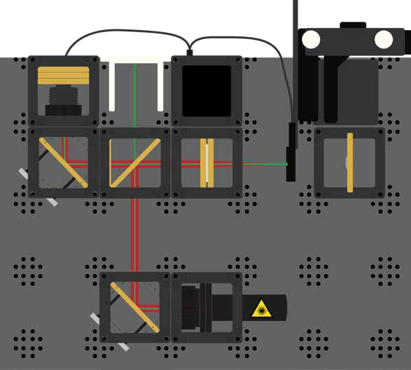
Diagram
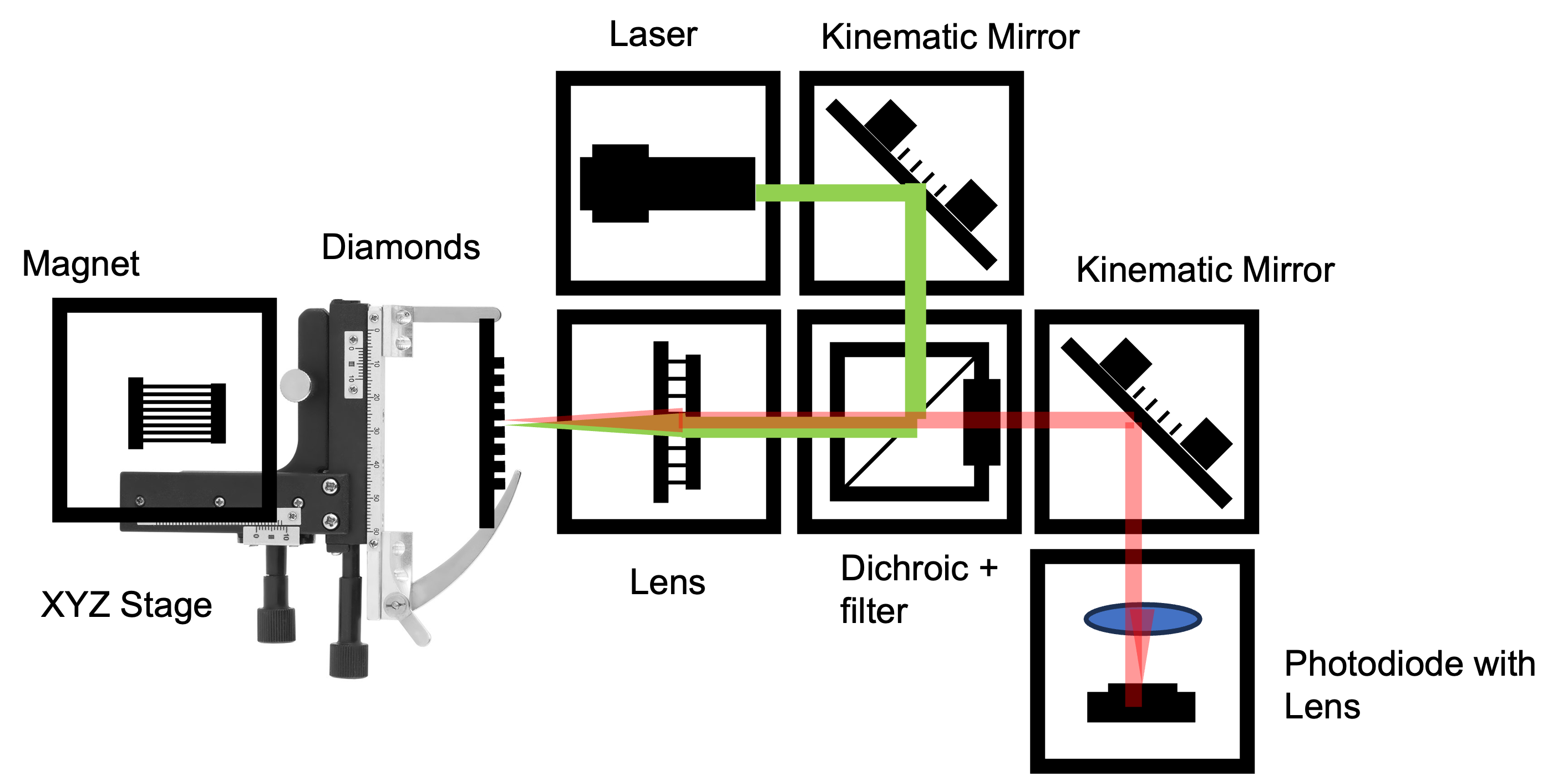 diagram showing ODMR setup layout with components labeled for easier understanding
Diamond's are a physicist best friend
NV stands for Nitrogen-Vacancy, referring to a diamond with a specific "impurity," usually visible as a pink coloration.
How Are NV Diamonds Formed? Diamonds consist of a carbon atom lattice. In an NV diamond, one carbon atom is missing and replaced by a nitrogen atom. A vacancy is left next to the nitrogen, creating the NV center.
What Makes NV Diamonds Special?
- Their spin states can be manipulated and read out via laser light, magnetic fields, and microwaves
- NV centers are stable quantum systems at room temperature, making them candidates for quantum computing
- They exhibit exceptional sensitivity to magnetic fields, electric fields, and temperature
- Single NV centers can be addressed and controlled optically
Tutorial: ODMR Setup
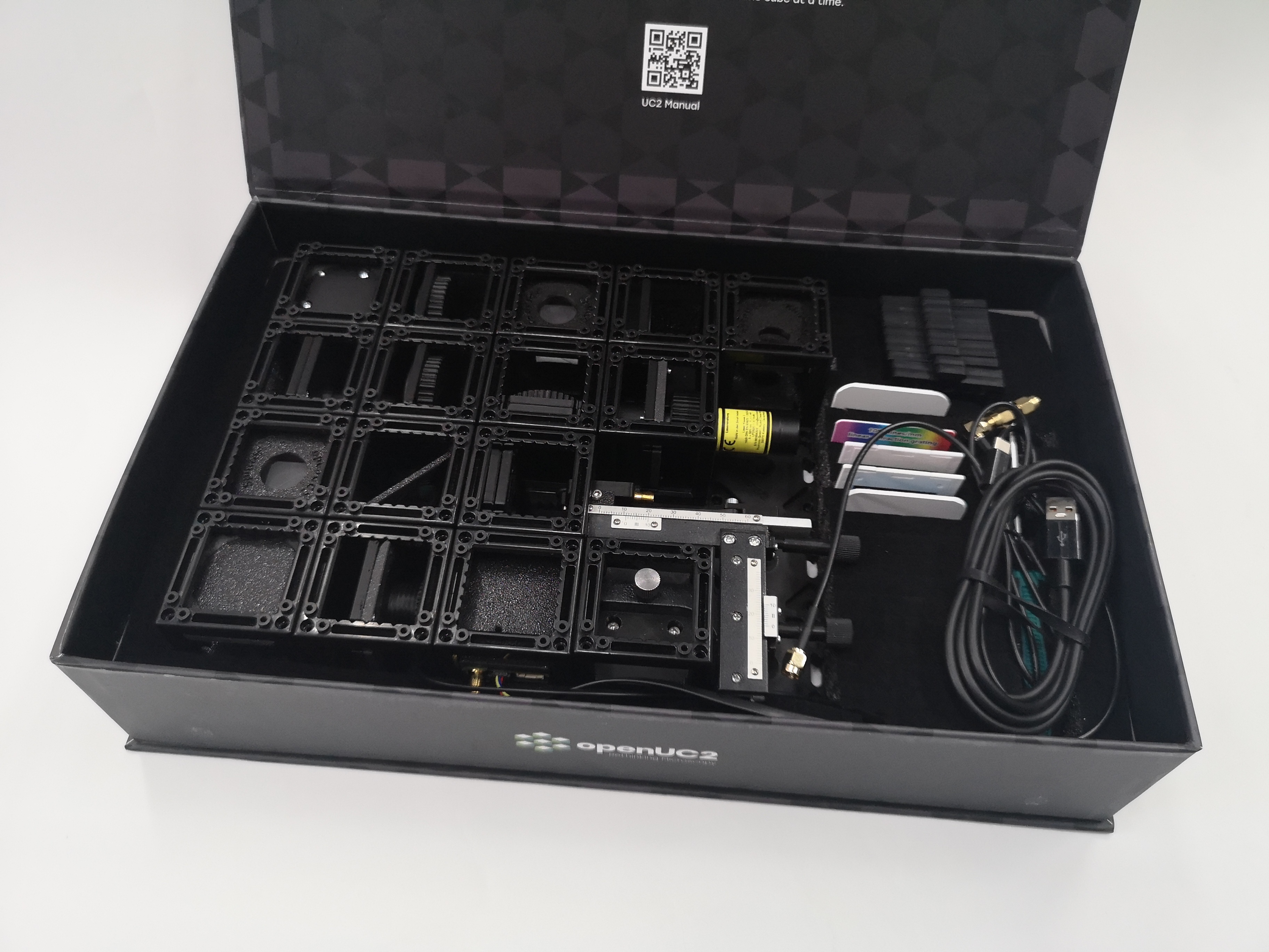
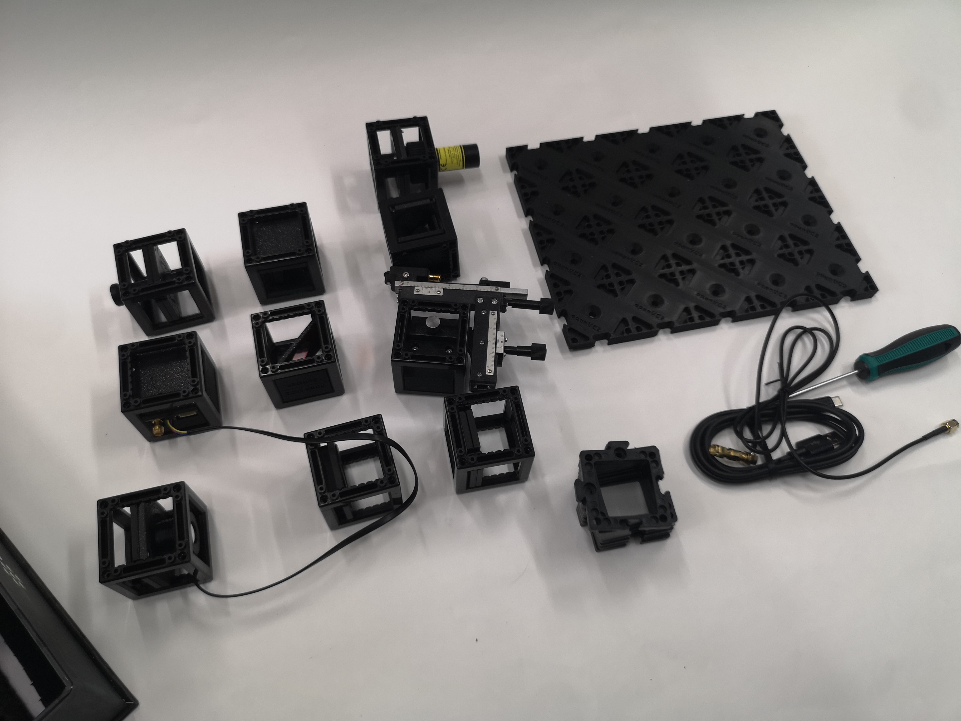
Materials Needed
- Base plate for mounting components
- Green laser diode (532 nm) for NV center excitation
- Two 45° mirrors for beam steering
- Beam splitter with filter for separating excitation and fluorescence
- Converging lens for focusing laser light
- Light sensor (photodiode) for fluorescence detection
- Electronics control box with microwave generation capability
- XY-stage with NV diamond sample
- Screen for initial alignment
- Color filter (red) for fluorescence isolation
- Magnet for applying external magnetic field
- Microwave antenna for spin manipulation
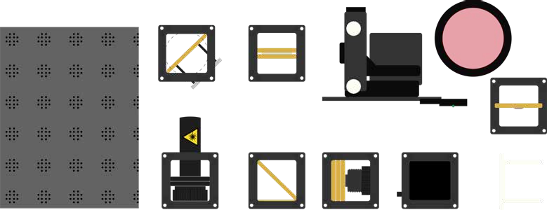
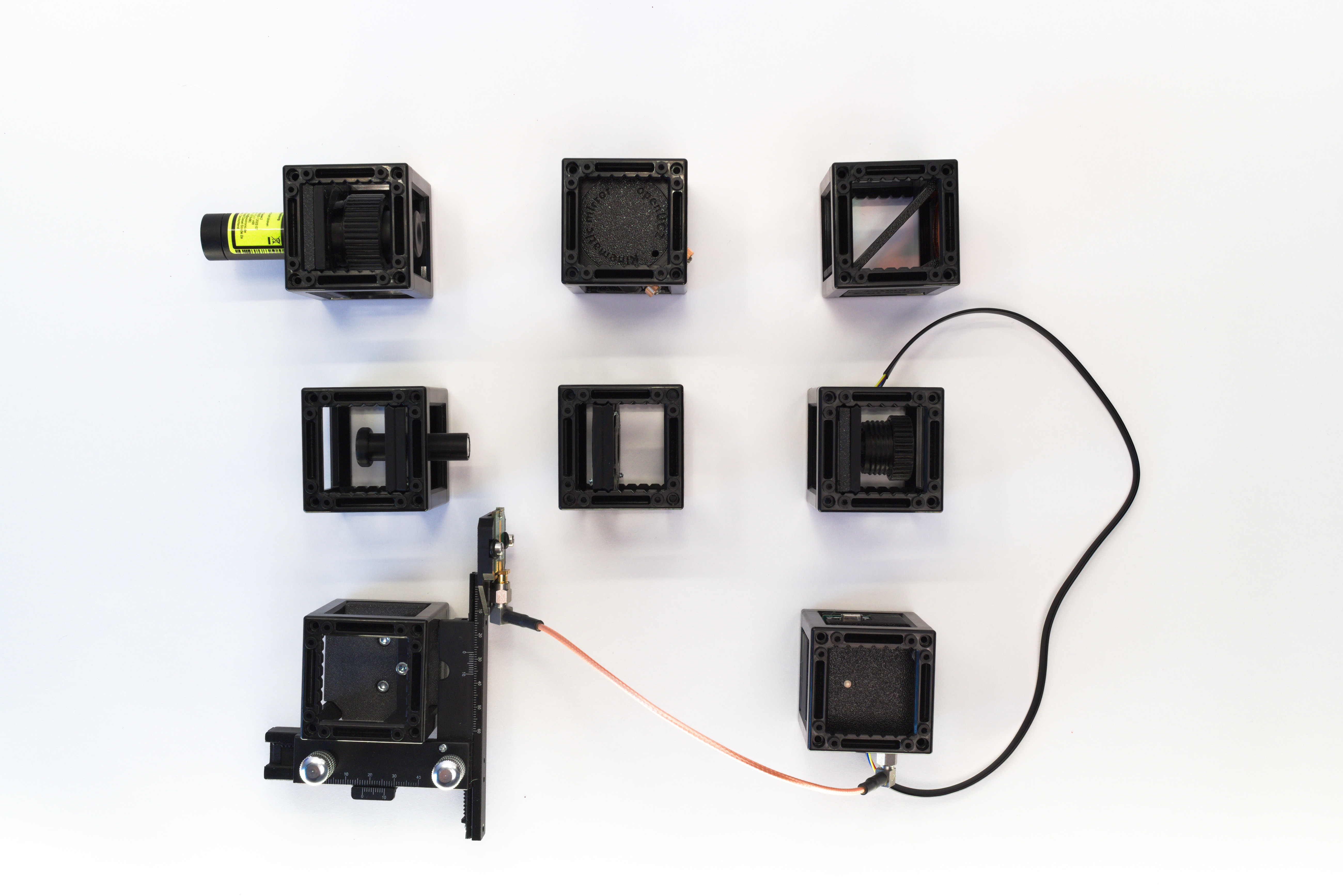
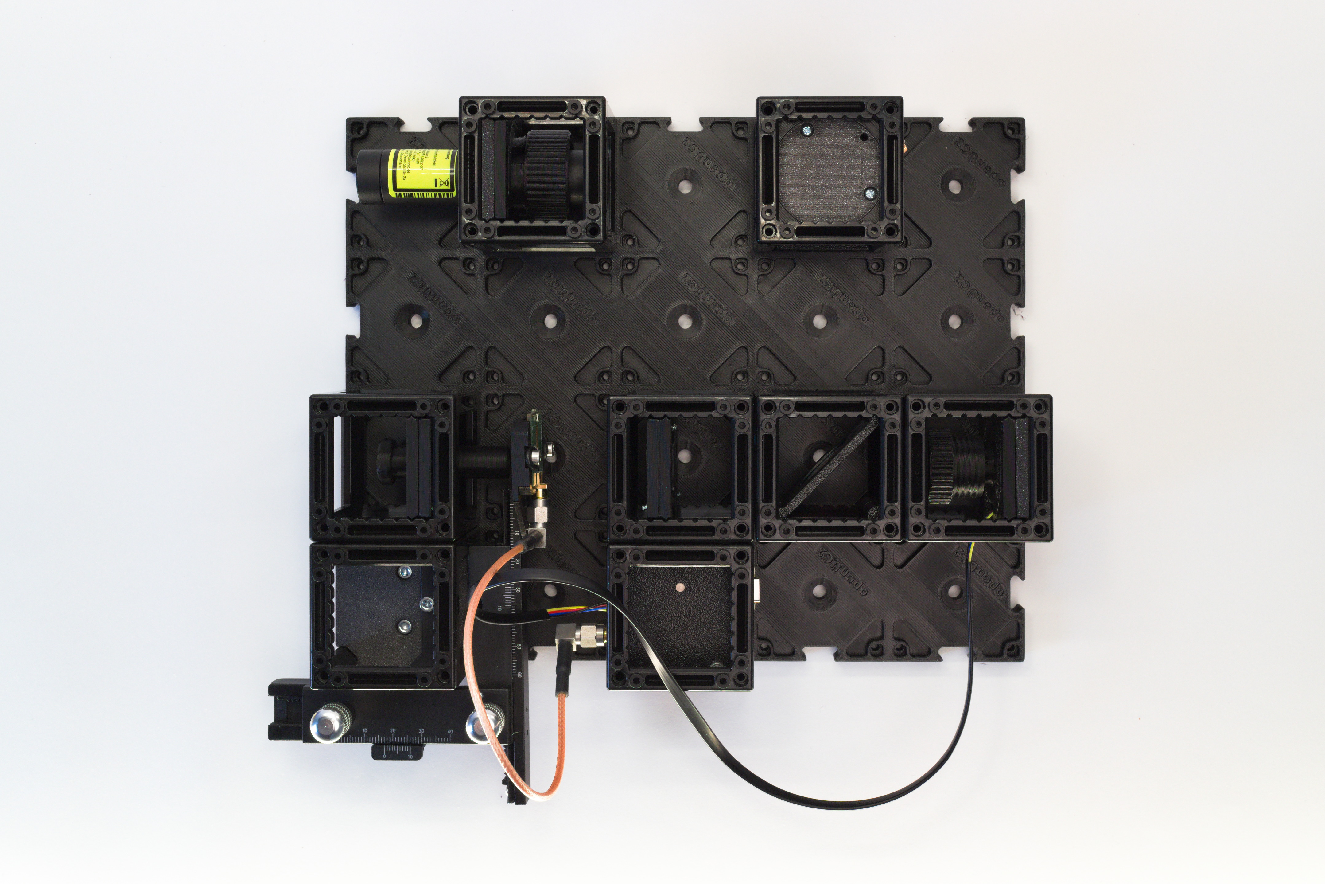
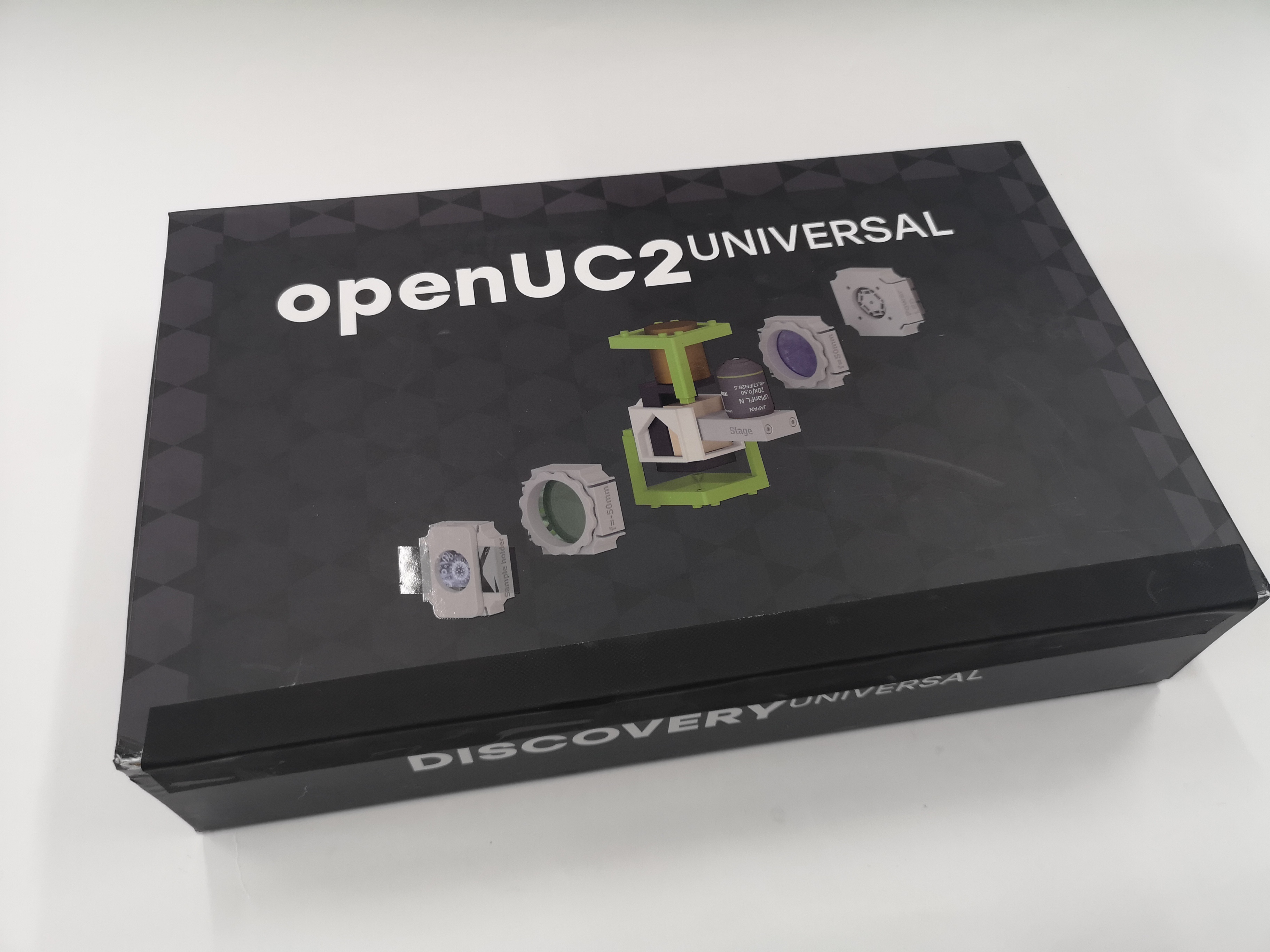
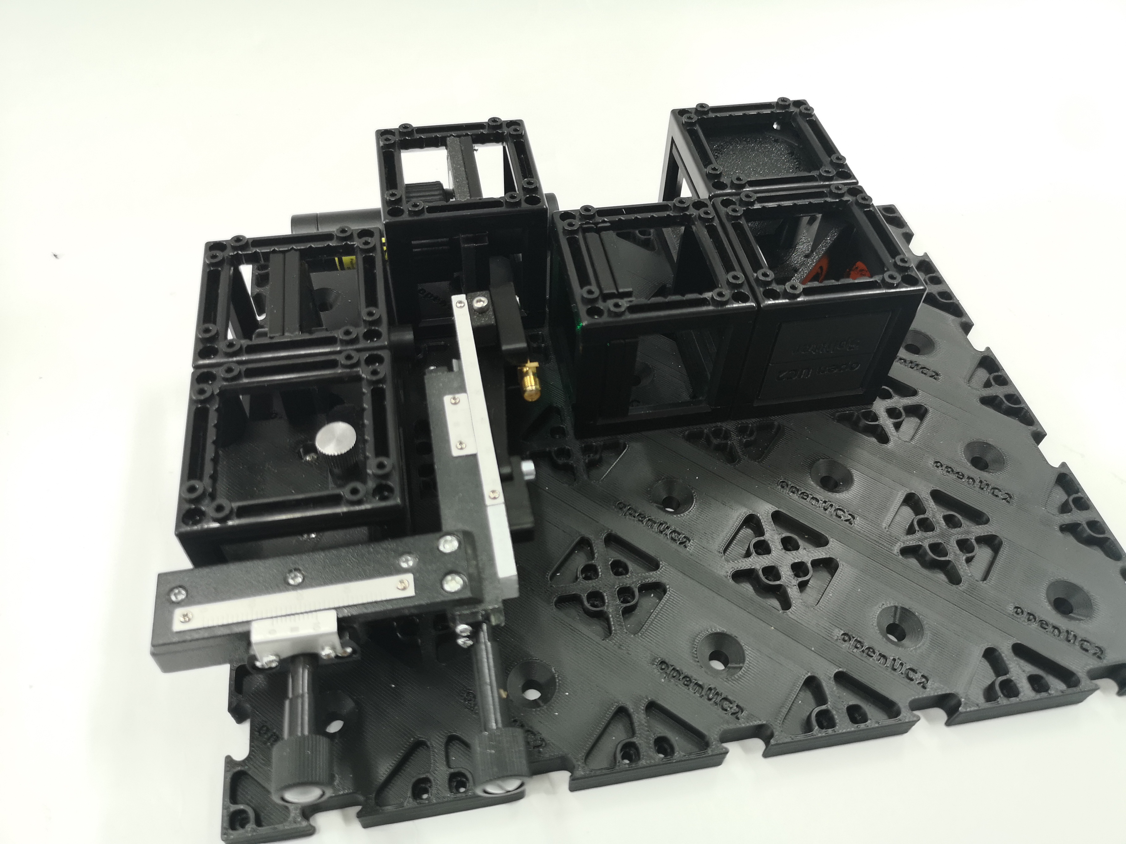
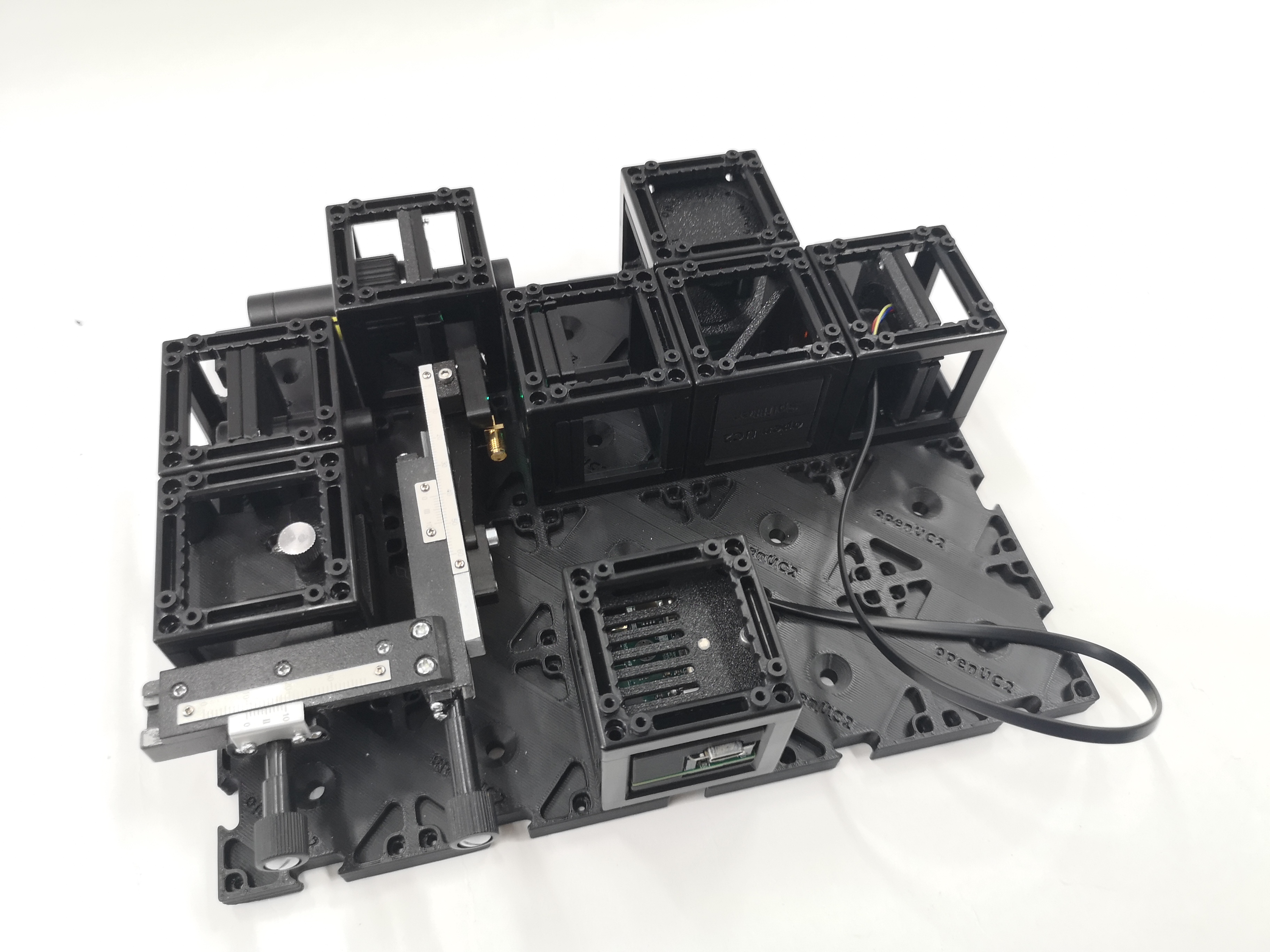
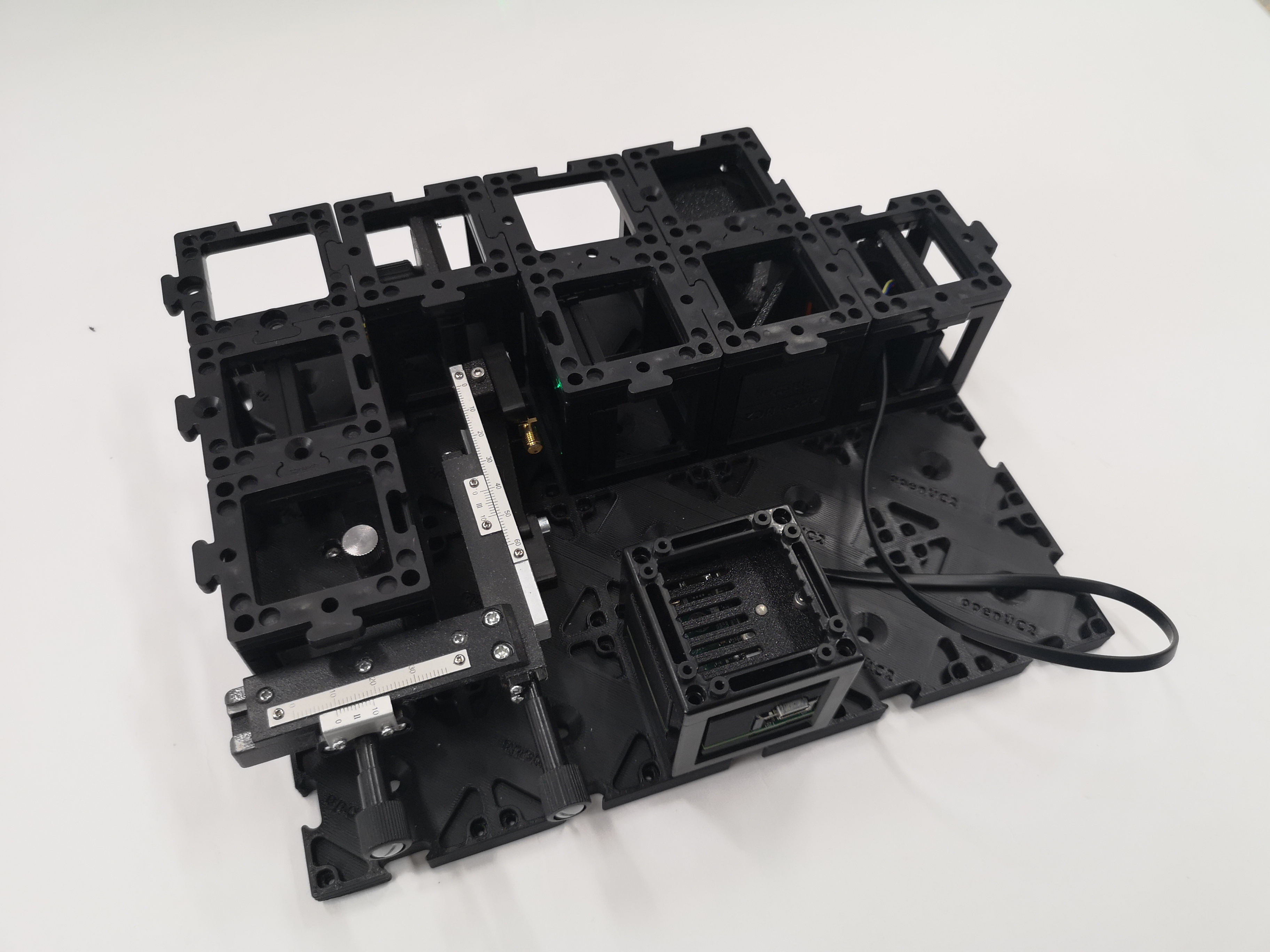
All components in the kit
Step 1: Assemble the Optical Components
This guide will walk you through the assembly step by step. You can follow the process according to the functional modules or refer to the diagram above for orientation.
SAFETY INSTRUCTIONS
⚠️ ATTENTION!
Laser Safety:
- The laser is only turned on when it is mounted on the base plate.
- The laser must be turned off each time it is repositioned.
- Before switching on, verify the direction of the beam. It should always run parallel to the table surface.
- Remove or cover reflective jewelry (rings, watches, bracelets).
- Remove reflective objects from the table (e.g. cases, rulers, wallets, phones).
- NEVER LOOK DIRECTLY INTO THE LASER! EYE WILL BE DAMAGED DIRECTLY
- NEVER SWITCH ON THE LASER WITHOUT INTENDED USE
- BEAM HAS TO GO AWAY FROM ONESELF - ALWAYS!
Magnet Safety:
- Individuals with implants must inform the supervisor. Special precautions may be necessary.
- Keep devices like phones, tablets, computers, and credit cards away from the experiment.
- Loose magnets must never be swallowed. Inform the instructor immediately if a magnet comes loose.
Optics Cubes:
- All gold-colored parts are functional components. (ATTENTION: The Colour may change. Typically, our inserts and cubes are black for laser-safety reasons!)
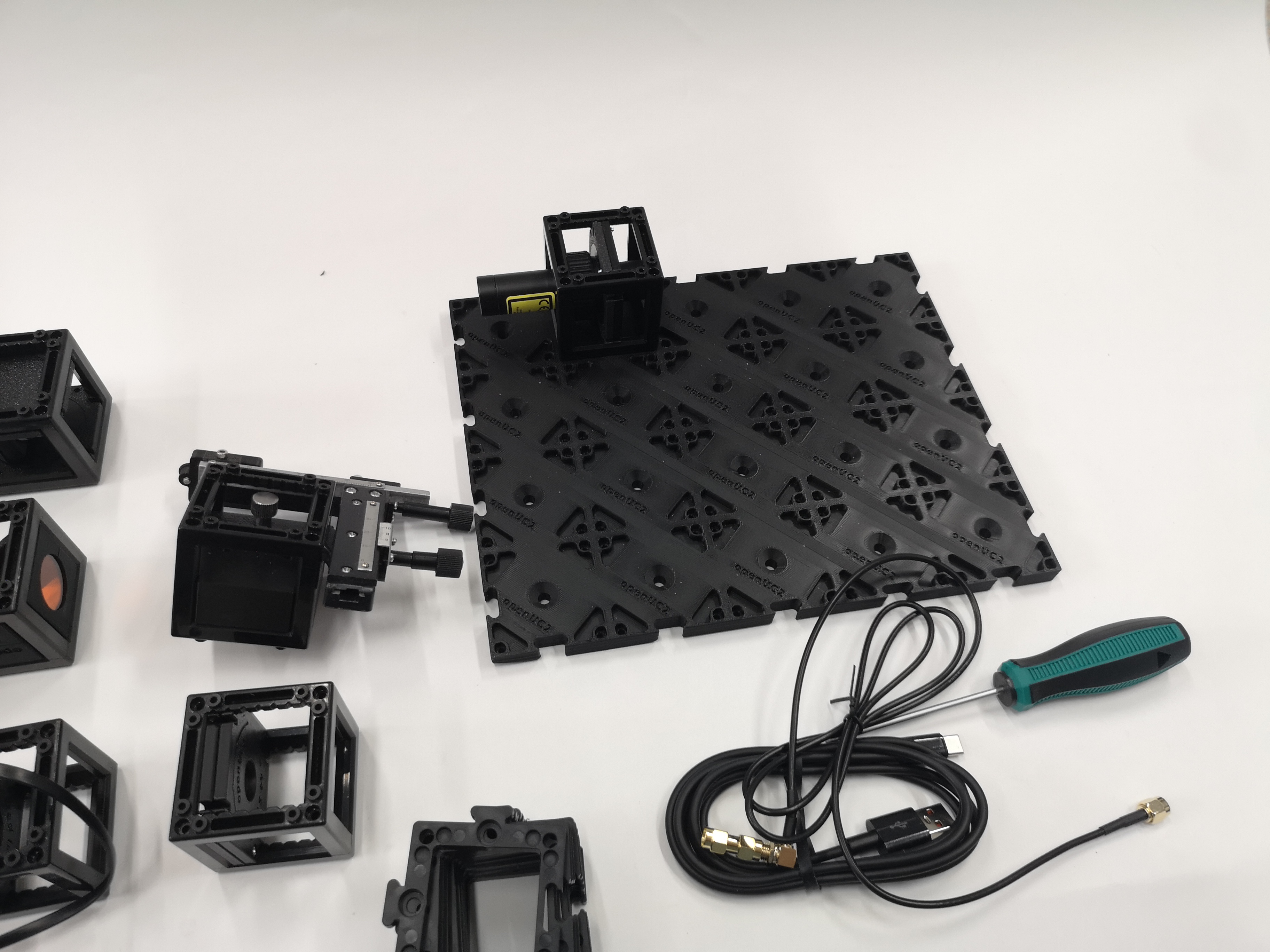
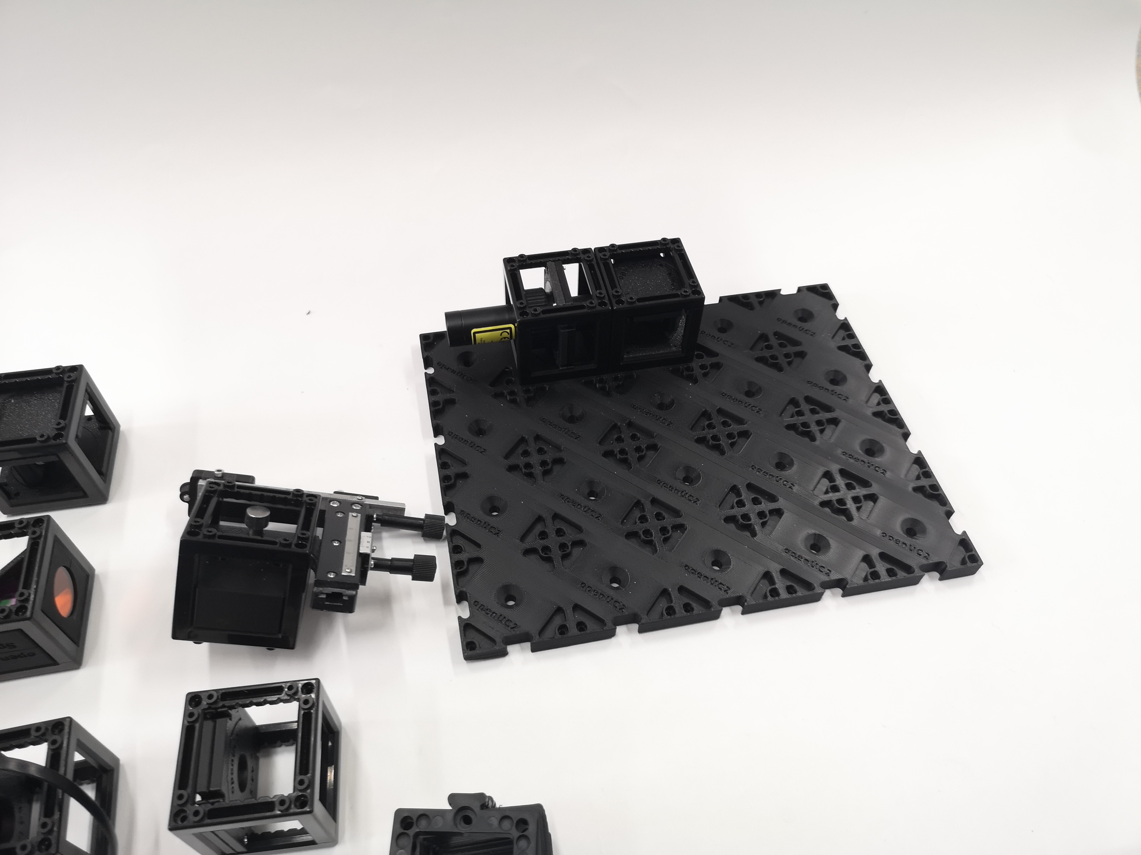
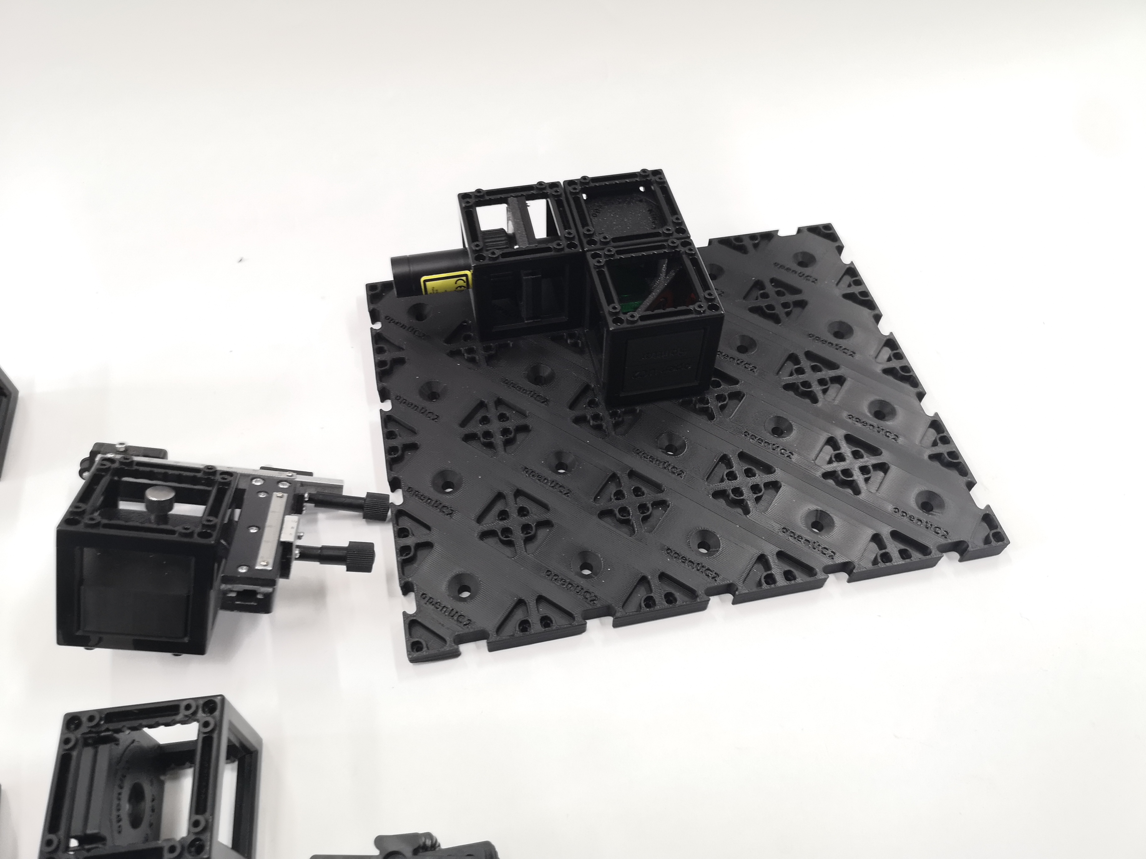
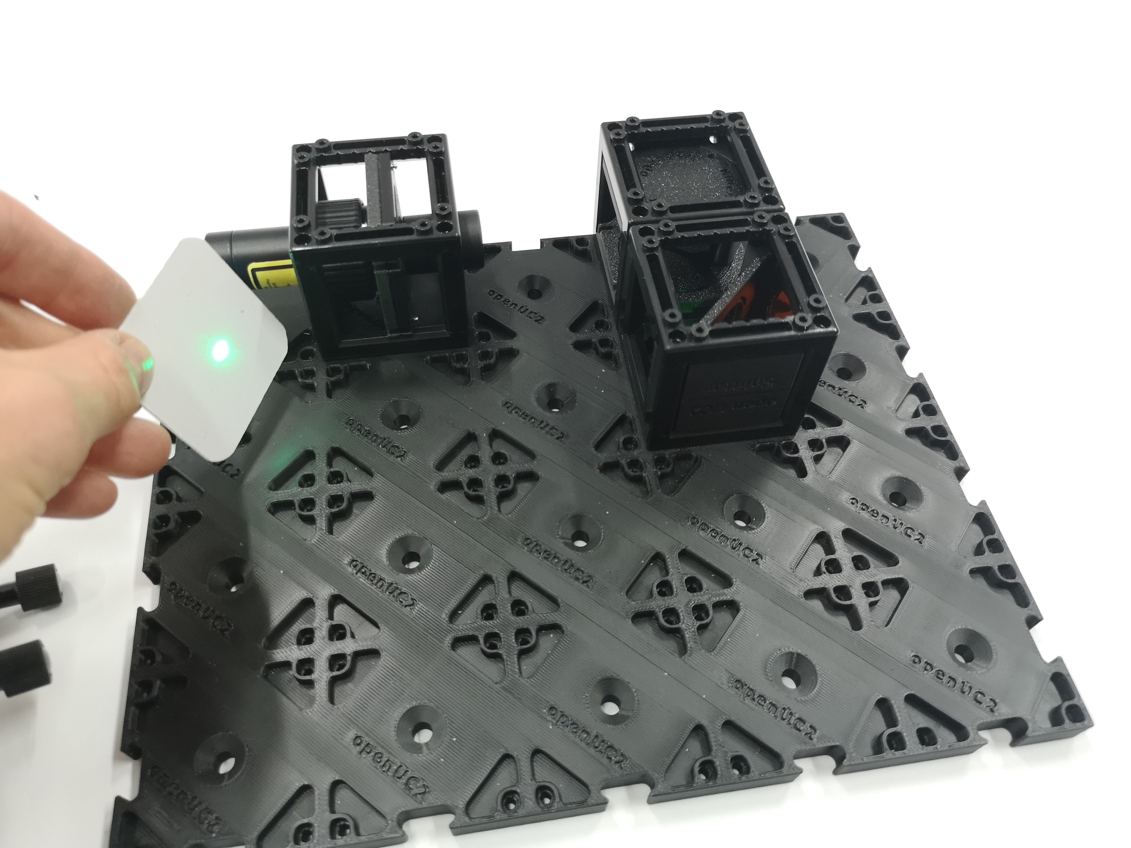
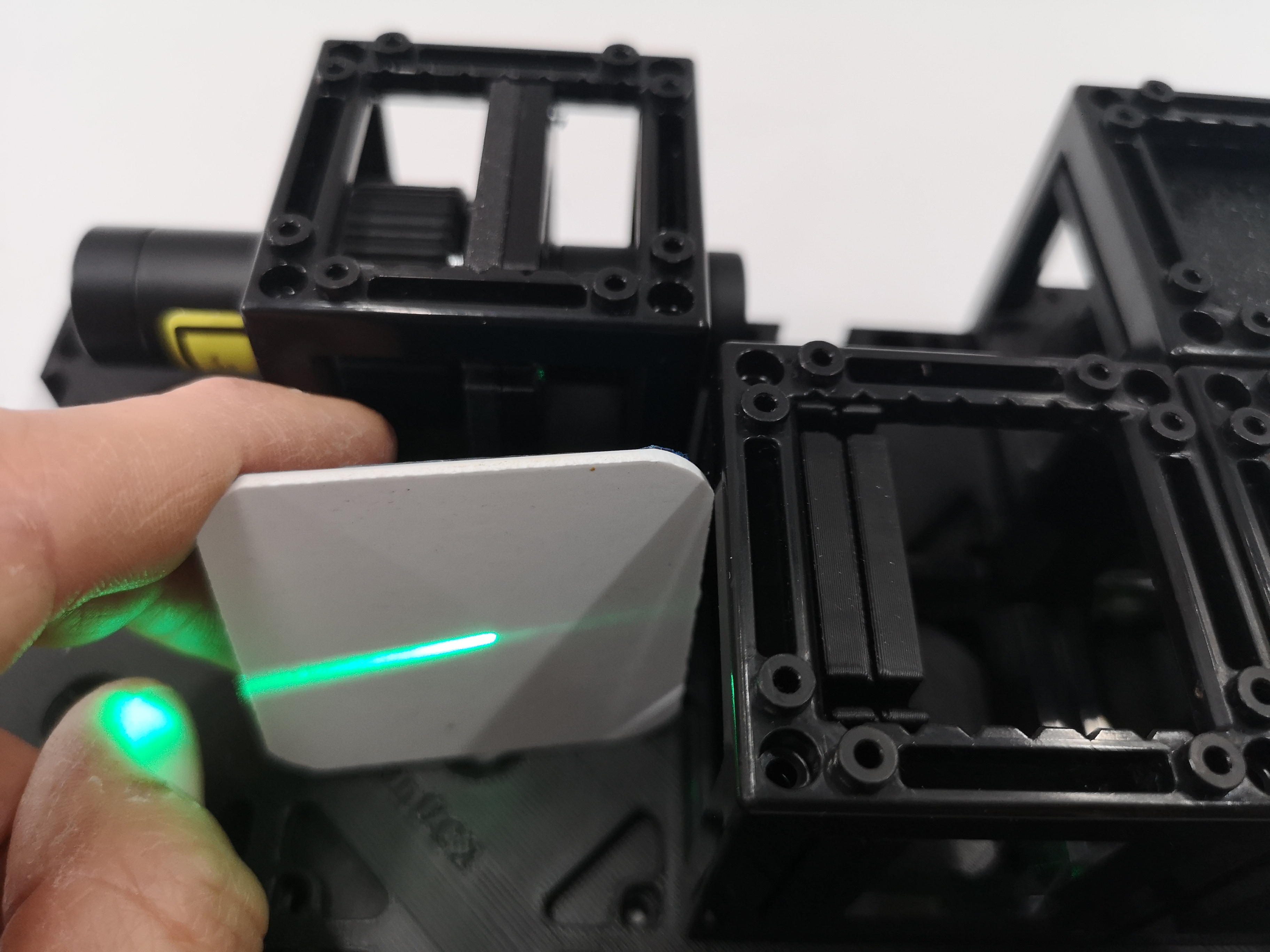
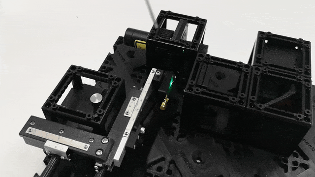
1.1: Build the Basic Optical Setup
Build the setup as shown in the diagrams. This creates a confocal microscopy configuration optimized for ODMR measurements. This is the basic configuration where the laser is focussed on the diamond and then the fluorescence signal is going back through the dichroic mirror mount to a detector.
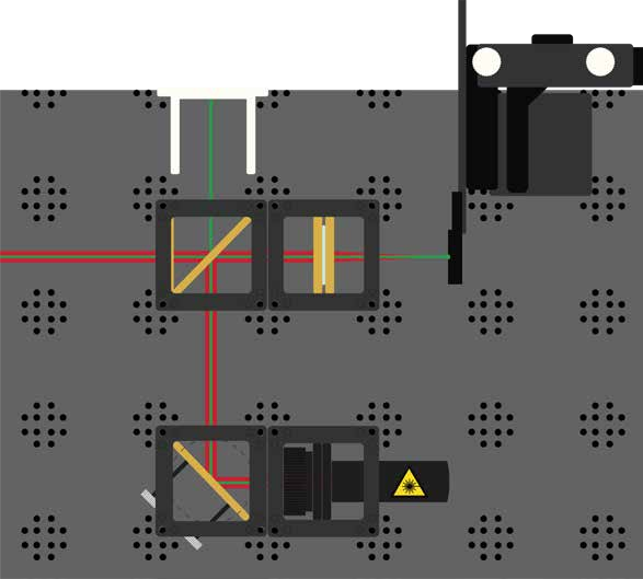
Description of a beamsplitter using openUC2 components on a grid, where the laser is reflected and fluorescence is transmitted

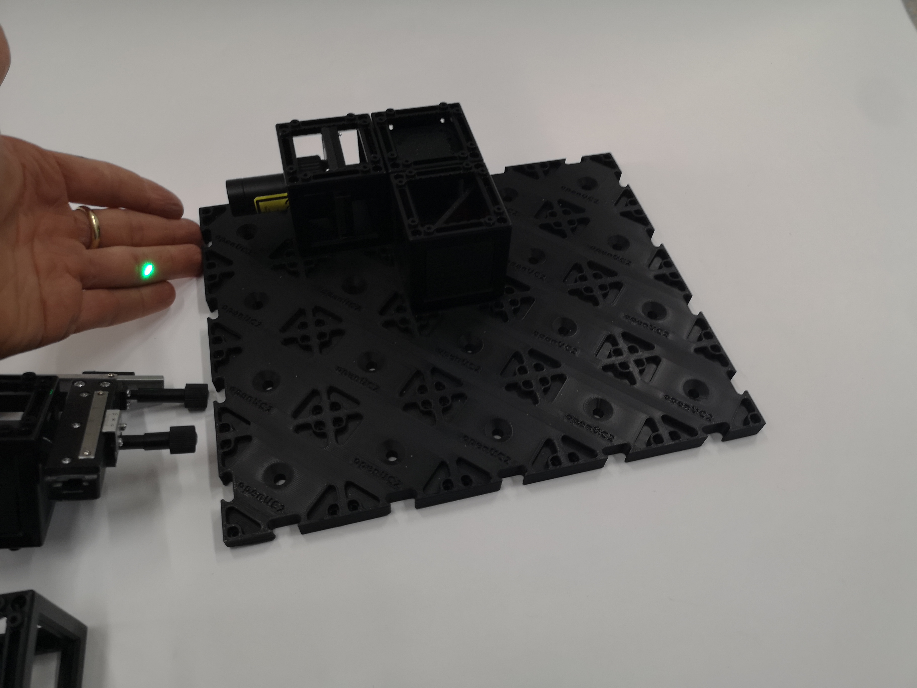
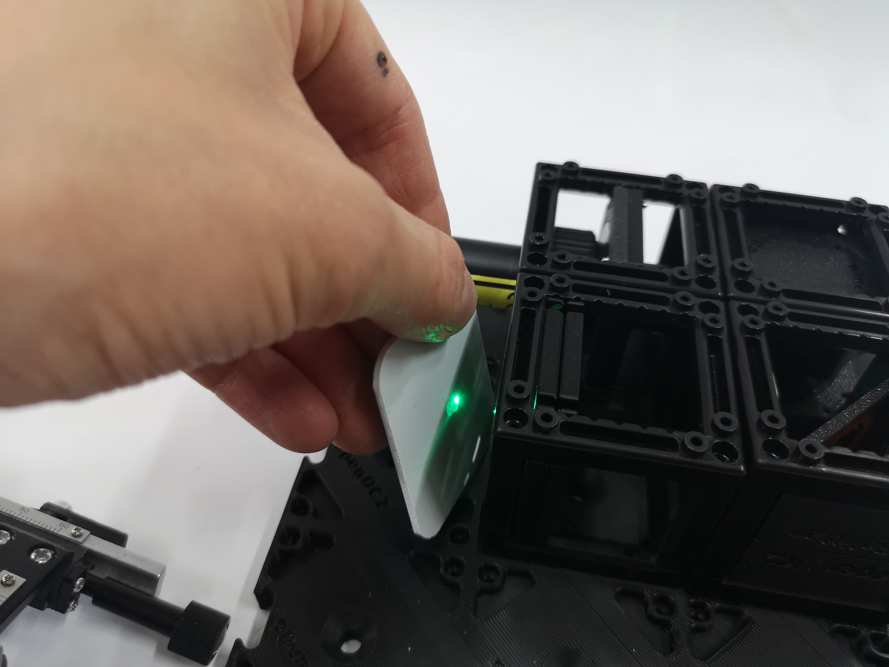
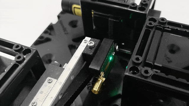
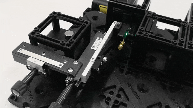
1.2: Laser Alignment
Align the laser so that it hits the center of the lens. The focused laser beam should create a small, bright spot when viewed through appropriate safety filters.
1.3: Diamond Positioning
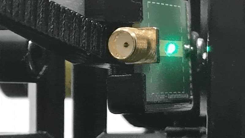
Adjust the XY-stage to place the diamond in the focus of the lens. The diamond should glow brightly when viewed through the red filter, indicating efficient excitation of the NV centers. The spot on the diamond should be smallest. This is achieved when the distance between the lens and the diamond PCB matches the focal length of the lens (40mm).
1.4: Complete the Detection Path
Complete the setup as shown in the figure. The detection path collects fluorescence from the NV centers and directs it to the photodetector.
Adjust the 45° mirror so that as much light as possible hits the light sensor for maximum signal collection efficiency.
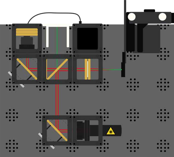
Step 2: Electronics
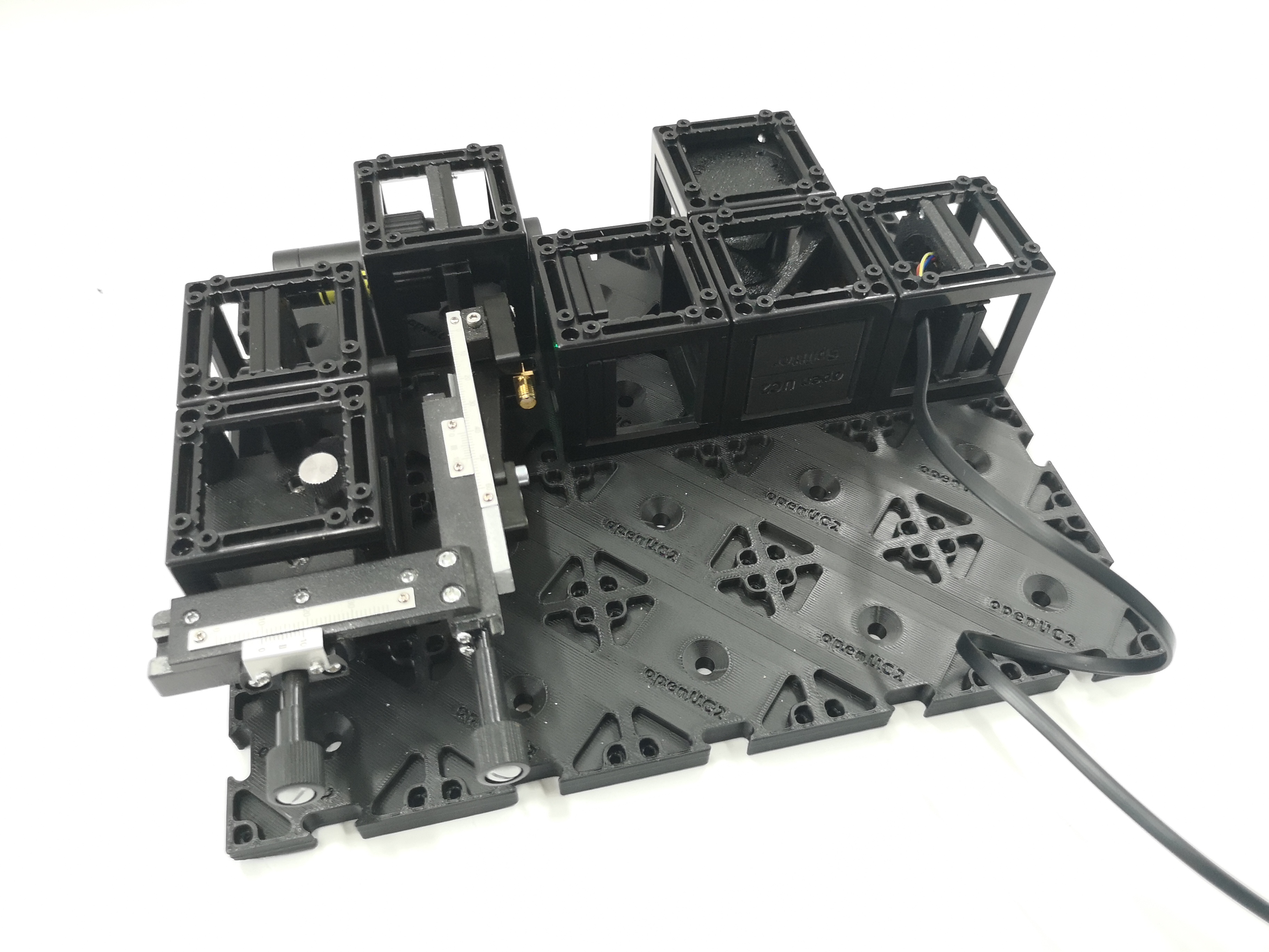
2.1: Plug in the Electronics as Shown Below
⚠️ Caution! If you need to change any of the cables or their position, always unplug the 12V power cable before doing so. Otherwise, the electronic components might get damaged!
Complete electronic setup image showing every wire connected correctly for ODMR: The photodiode connects to the ESP32s3 board via the I2C Stemma cable and the antenna connects to the board via the SMA cable
- the laser diode has its own battery, so you can use the switch in the rear
- Connect the photodiode to the I2C input port
- Connect the microwave antenna to the control box
- Connect the XY-stage motors if available
- Plug in the USB-C at your ESP32 and connect to your PC.
- TODO: Add specific ODMR electronics wiring diagram
2.2: Flashing the ESP32 Firmware
- Before proceeding, ensure your ESP32 board has the latest firmware. You can download and flash the firmware via the official openUC2 website, selecting your version (most likely ESP32C3 ODMR Quantum Mini Labs)), then click on the
connectbutton.
The source code can be found here.
Connect the ESP32 to your computer using the USB-C cable.
In your Chrome browser, a dialog will prompt you to select the COM port for your ESP32, which should be shown as
CP2102 USB to UART Bridge Controlleror alike. Once connected, you can install the latest firmware by simply clicking the "Install" button.Wait until the firmware has been successfully flashed.
2.3: Connecting to the Web Interface
After flashing the firmware - unplug and replug the ESP and wait for a wifi Hotspot to appear. Something like ODMR-XXXX. Connect to that and go to http://192.168.4.1
Alternatively you can go to https://youseetoo.github.io/odmr and connect to the board via Web-Serial (web serial tab).
2.4: Testing in the Web Interface
Control the various components via the web interface:
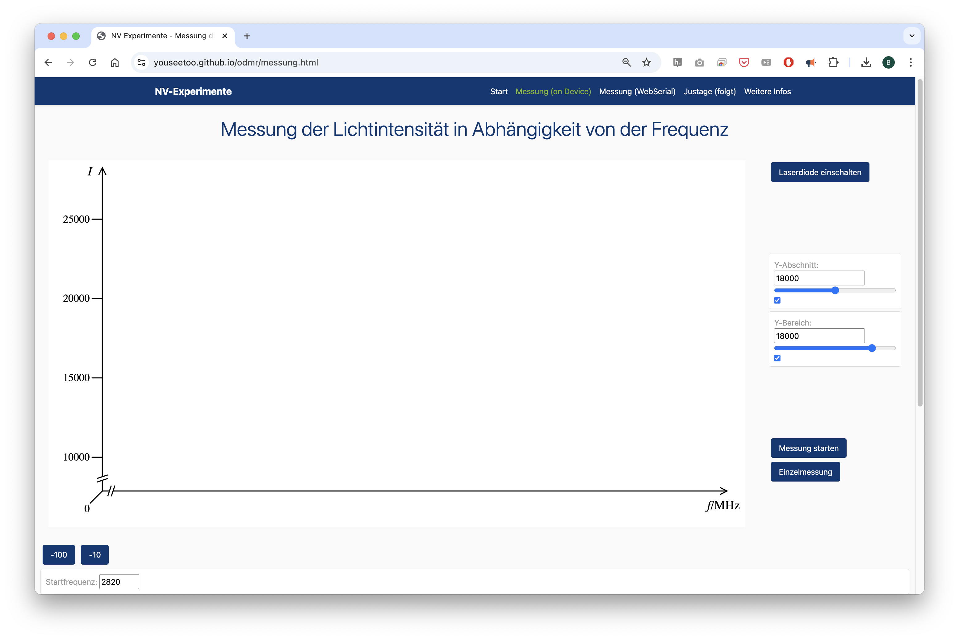
- Monitor photodiode signal levels
- Test microwave output (frequency sweeps)
When starting an acquisition, you should see the frequency go through the min/max values by step increments.
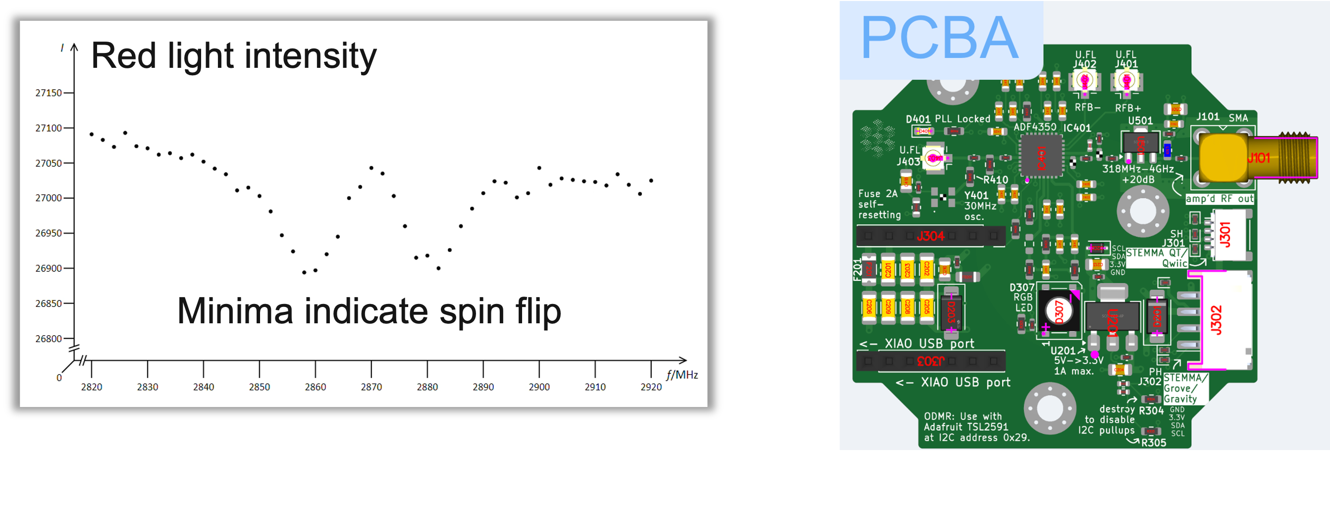
ODMR Electronics and fluorescence response
Step 3: Aligning the ODMR Setup
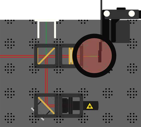
3.1: Microwave Integration
Connect the microwave antenna to the control box and position it near the diamond sample.
Install the magnet cube in the setup. The magnet provides an external magnetic field that will split the ODMR resonance lines.
3.2: Signal Optimization
Observe any intensity changes when changing the magnet's position. This demonstrates the magnetic field dependence of the NV center fluorescence.
3.3: Fine Alignment
Optimize the setup for maximum fluorescence signal and best signal-to-noise ratio by adjusting:
- Laser focus on the diamond
- Collection efficiency of fluorescence
- Microwave coupling to the NV centers
3.4: Aligning the Laser
Ensure the laser beam is aligned with the optical axis of the "Confocal" microscope. The laser should be focused on the diamond surface, creating a small, bright spot.
Setting up the ODMR setup with images

Experiment 1: Basic ODMR Signal Detection
1.1: Establish Baseline Fluorescence
Turn on the laser and measure the baseline fluorescence signal from the NV centers without microwave excitation. Record the signal level and stability.
TODO: Add image of baseline fluorescence measurement
1.2: Apply Microwave Radiation
Turn on the microwave source and sweep through frequencies around 2.87 GHz while monitoring the fluorescence intensity.
1.3: Observe ODMR Dip
Look for the characteristic dip in fluorescence at the resonance frequency. This indicates successful spin manipulation of the NV centers.
TODO: Add example ODMR spectrum showing the characteristic dip
Experiment 2: Magnetic Field Measurement
2.1: Zero-Field Measurement
Record the ODMR spectrum without the external magnet to establish the zero-field splitting.
2.2: Apply External Magnetic Field
Position the magnet at various distances from the diamond and record how the ODMR spectrum changes.
2.3: Analyze Zeeman Splitting
Observe how the single ODMR line splits into two lines as the magnetic field increases. Measure the frequency separation to determine the magnetic field strength.
TODO: Add example data showing Zeeman splitting at different magnetic field strengths
Experiment 3: Advanced ODMR Techniques
3.1: Pulsed ODMR Measurements (comming soon as Coherent Control)
TODO: Add instructions for pulsed measurement techniques if hardware supports it
3.2: Spatial Mapping
Use the XY-stage to map ODMR signals across the diamond sample, revealing spatial variations in NV center properties.
3.3: Temperature Dependence
TODO: Add instructions for temperature-dependent measurements if applicable
What We Measure and Learn
Through this experiment, students learn:
- How quantum systems can be manipulated and measured optically
- The relationship between magnetic fields and quantum spin states
- How microwave radiation can affect electron transitions
- The principles behind confocal microscopy and fluorescence detection
- Real-world applications of quantum sensing technology
Technical Details of the ODMR Process
The goal of the ODMR setup is to understand how we can optically measure magnetic fields through the reduction of fluorescence in the resonance case when microwaves interact with a diamond. This effect is interesting for indirectly measuring magnetic fields precisely through optical readout.
What we specifically measure is the resonance of the defect site in a diamond with NV centers. We have small diamonds with a diameter of approximately 100 nanometers and several NV sites placed on a circuit board that serves as an antenna. We excite these with laser light of a specific wavelength. Even without applied microwaves, we can measure the fluorescence of the diamond. This means we excite the diamond with green light (532 nanometers) and can measure the emissions in the red spectrum (over 600 nanometers).
The core idea is that when we apply microwaves, we can observe the Zeeman effect by splitting the spin-flip into negative and positive components, where the reduction in fluorescence shifts symmetrically to the respective negative and positive parts relative to the positive or negative spin.
Modern Applications
NV diamonds are currently used in basic research and ODMR prototypes. Future applications include:
- Use as quantum sensors (e.g., temperature, magnetic field, pH values inside cells)
- Application in nuclear magnetic resonance (as a supplement to MRI)
- Use as stable, controllable qubits in quantum computers
The QuantumMiniLabs Project
The QuantumMiniLabs project is developing an open-source ecosystem that enables low-cost, scalable, modular, and repairable quantum tech experiments. The goal is to deploy the system at 100 educational locations across Germany.


QuantumMiniLabs offer the first affordable DIY platform for experimenting with second-generation quantum systems. NV diamonds allow for stable experiments at room temperature.