GalvoIntro
mAIkroscope Galvo Interface Board – Extended Hardware & Firmware Documentation Rev A – 26 May 2025
1 Purpose & Key Features
- Dual-axis galvo driver interface for UC2 microscopes.
- Seeed XIAO ESP32-S3 MCU handles scan synthesis and trigger generation.
- On-board 12-bit SPI DAC (MCP4822) creates ±10 V differential XY signals for low-cost Chinese galvo drivers.
- Three independent 50 Ω trigger outputs (pixel, line, frame).
- CAN 2.0B bus for remote control via UC2-CAN protocol.
- Integrated ±12 V/3.3 V/5 V analog rails, 2 A output budget for external driver modules.
This is a scan using the Flimlabs.com software, their detector and their pulsed lasers. This is a 512x512 pixel^2 area
2 System Architecture
ESP32-S3  ↔  SPI  ↔  MCP4822  →  LM324 diff amps  →  SMA L± / R±
            │              │                     ├─ pixel/line/frame triggers
            │              │                     └─ U.FL laser blanking
            └─ TWAI CAN bus → SN65HVD230 → JST-XH backbone
- Two-phase DAC update: write 12-bit sample into DAC register (CS low), then pulse LDAC to latch both channels simultaneously; saves one SPI transaction per point.
3 Electrical Specifications
| Parameter | Value | Comment | | | - | -- | | - | | Backbone input | 12 V ±5 % | via J1001-1 | | | Board self-consumption | ≈ 50 mA | excludes external galvo drivers | | | Galvo supply pass-thru | ±12 V, 2 A max | J1004/J1007/J1008 | | | DAC resolution / range | 12 bit, 0 – 3.3V at 4096 steps | converted to ±10 V diff | | | Output bandwidth | ≈ 25 kHz (-3 dB) | limited by LM324 stage | | | Trigger level | 3.3 V CMOS, 50 Ω back-terminated | SMA J1009-J1011 | | | CAN bus | ISO11898-2, 1 Mbit/s default | 120 Ω terminator selectable (JP2001) | |
4 Connectors & Pinouts (summary)
- Power + CAN (J1001, JST-XH-4): GND, +12 V, CAN_H - CAN_L
- Galvo power out (J1004 big Molex 3.96 mm, J1007/J1008 KF2510): ±12 V, GND – pin order matches driver boards.
- Differential XY (J1005/J1006, SMA-3): L+, L-, GND and R+, R-, GND.
- Triggers (SMA-2): Pixel (J1009), Line (J1010), Frame (J1011).
- Laser blanking (J10001, U.FL): single-ended 50 Ω.
- XIAO headers (J1002/J1003): break out all ESP32-S3 I/O; see GPIO map in §7.
5 Analog Signal Chain
- MCP4822-E/SN generates 0-3.3 V (12-bit).
- Gain/offset network (LM324) maps 0 V→0 V, ±2.048 V→±10 V.
- Second LM324 stage inverts each leg, giving true differential L± and R±.
- Outputs drive ≥ 20 mA into the 10 kΩ inputs of typical galvo amps.
- LC filters on ±12 VA rails set 50 Hz cutoff to suppress switching noise.
6 Power Subsystem
- TPS5430 buck: 12 V → 3.3 V @ 0.8 A for MCU/CAN.
- TPS5430 inverting buck-boost: 12 V → −12 V @ 1.5 A for op-amps.
- 78L05 linear: 5 V A for DAC/reference.
- All rails filtered by π-LC networks; testpoints TP400x provided for bring-up.
7 Firmware Overview
// Default pin mapping (Arduino style) on XIAO systems
#define PIN_DAC_CS       8   // J1003-10 / GPIO8
#define PIN_DAC_SCK      7   // J1003-9 / GPIO7
#define PIN_DAC_SDI      9   // J1003-11 / GPIO9
#define PIN_DAC_LDAC     6   // J1002-6 / GPIO6
#define PIN_TRIG_PIXEL   2   // GPIO2
#define PIN_TRIG_LINE    3   // GPIO3
#define PIN_TRIG_FRAME   4   // GPIO4
#define PIN_CAN_TX       5   // GPIO5
#define PIN_CAN_RX       44  // GPIO44
#define PIN_LASER        43  // GPIO43
#define PIN_PUSHBUTTON   1   // GPIO1 (enable internal pull-up)
Loop structure:
for each Y line:
    for each X pixel:
        write X,Y to DAC; assert TRIG_PIXEL
    assert TRIG_LINE
assert TRIG_FRAME
Coordinate depth: 12 bit full-scale → map image size (e.g. 512 × 512) by
coord = (pixel * 4095) / (size-1).PlatformIO project: clone
openUC2/galvo-interface-fw, selectenv:xiao_esp32s3, build & upload via USB-C.UC2-CAN commands: Coming soon
8 Typical Operating Procedure
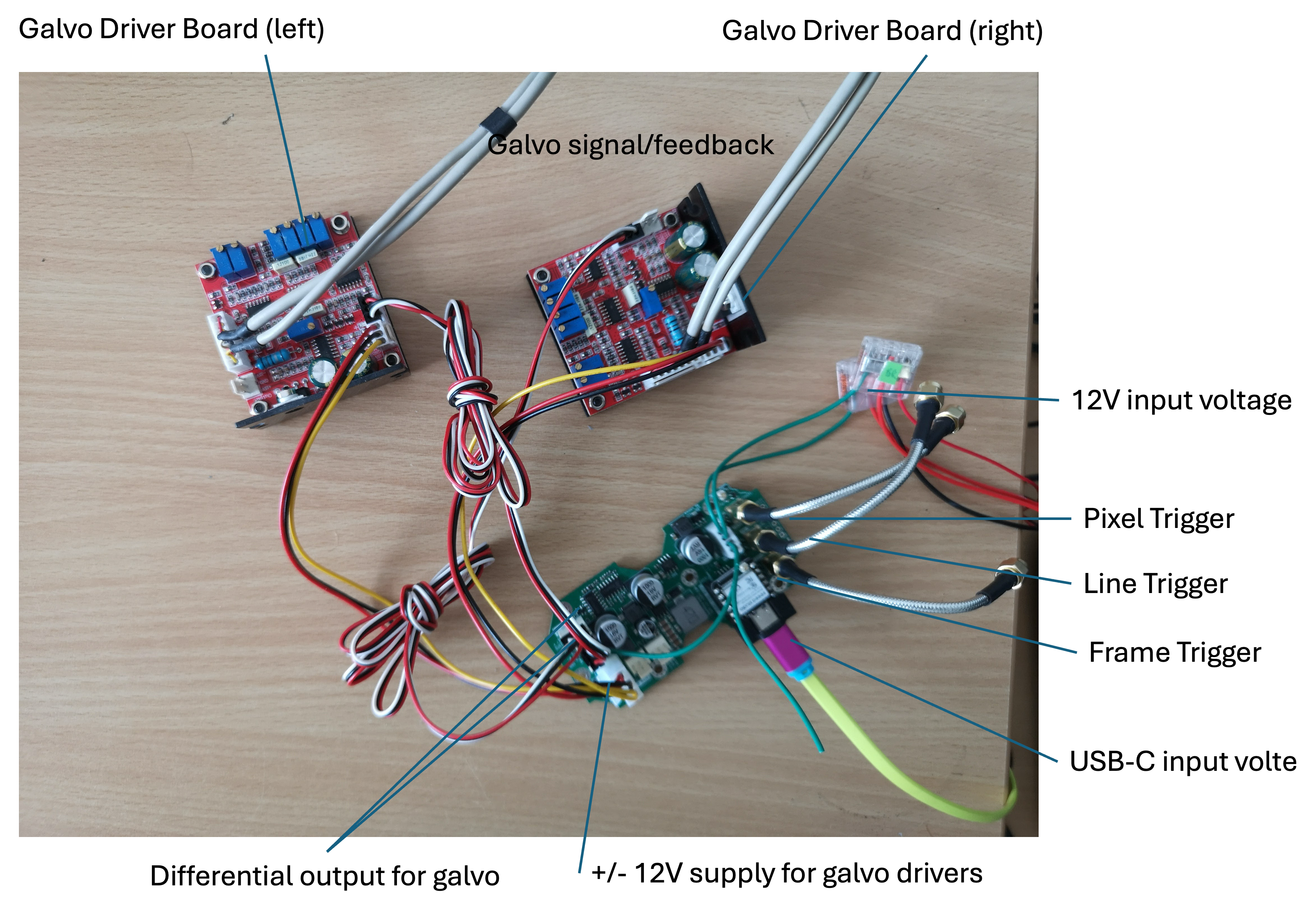
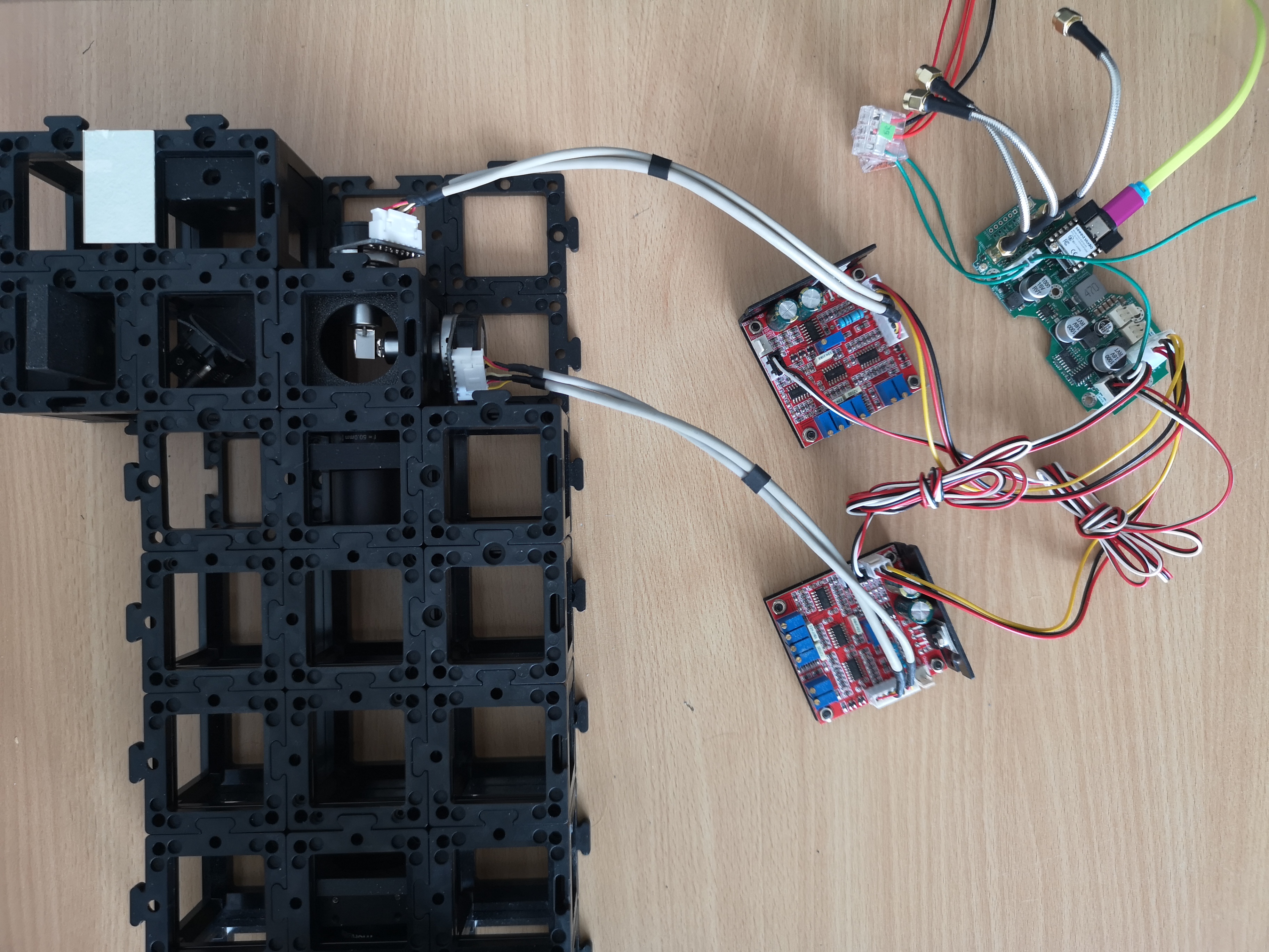
- Feed 12 V from microscope backbone into J1001-1 (CAN connecotr); connect CAN (optional), you can supply 12v/GND via the JST 4 Pin sconnector.
- Connect each galvo driver board with 3-pin power and SMA signal leads.
- Flash firmware; set parameters in firmware for min/max pixel and stepsize as well as pixel dwell time
- Monitor pixel trigger on oscilloscope
- Tune galvo PID on driver boards for minimal overshoot
9 iBOM
10 Firmware Architecture (openUC2-LaserScanner)
You can find the files here https://github.com/openUC2/openUC2-LaserScanner/blob/main/src/main.cpp
The UC2-ESP Firmware also has the CAN-enabled version of it in its code base here: https://github.com/youseetoo/uc2-esp32/blob/main/main/src/scanner/GalvoController.cpp
:::warn Sometimes the XIAO cannot be flashed immediately, for this you have to press boot and reset while firmware is flashed - or erase the firmware first using this tool: https://espressif.github.io/esptool-js/ :::
| Layer | Key files | Function |
|---|---|---|
| Application | src/main.cpp | Instantiates SPIRenderer, updates parameters in a while(1) loop, and calls start(); disables the watchdog and raises log level to warn for GPIO. (GitHub) |
| Render Engine | src/SPIRenderer.{h,cpp} | Converts image geometry into DAC samples, handles SPI transfers, and asserts pixel/line/frame triggers with single–cycle GPIO writes. Implements setParameters(), draw(), start(). (GitHub) |
| Board-select macros | same header | IS_XIAO, IS_XIAO_UC2GALVOBOARD choose the correct pin map at compile time. (GitHub) |
| Build system | platformio.ini | Two build environments: esp32dev (generic) and UC2_3_Xiao (Seeed XIAO ESP32-S3). Both use ESP-IDF with Arduino component; UART at 921 kbit s⁻¹. (GitHub) |
11.1 File structure
openUC2-LaserScanner
├── src/                 # C++ sources
│   ├── main.cpp         # app_main() entry point
│   ├── SPIRenderer.cpp  # raster engine
│   └── SPIRenderer.h
├── include/             # (optional) extra headers
├── lib/                 # third-party libs, e.g. UC2-CAN
├── python/              # helper scripts (ILDA, LUT generation)
├── KICAD/               # electrical design
├── platformio.ini       # build targets
└── sdkconfig.*          # pre-tuned IDF configs
11.2 Build flow (PlatformIO)
- Select UC2_3_Xiao in platformio.ini.
pio run→ ESP-IDF CMake → compile + link with Arduino component.pio run -t uploadflashes over USB-CDC (921 kbit s⁻¹).- Partition scheme
custom_partition_esp32s3.csvreserves PSRAM cache and 1 MiB for OTA.
11.3 Runtime tasks
| Task | Core affinity | Duty |
|---|---|---|
| mainTask (app_main) | core 0 | parameter sweep, calls renderer, yields 10 ms to scheduler. |
| IDF idle0/1 | core 0/1 | housekeeping (watchdog disabled for main). |
| Additional tasks (optional) | — | CAN listener, WebSocket, or CLI can be added; use xTaskCreatePinnedToCore. |
The code presently runs everything in the foreground; heavy processing (e.g. CAN command parsing) should be off-loaded to a FreeRTOS task to keep the raster loop deterministic.
11.4 SPIRenderer workflow
constructor()
  ├─ configure GPIO for laser, LDAC, triggers
  ├─ initialise SPI3 @20 MHz (XIAO) or HSPI (generic)
  └─ pre-compute nX, nY from (X_MIN…X_MAX)/STEP

start()
  └─ draw()

draw()
  for each frame
    assert all triggers high    ← frame start
    for X = X_MIN…X_MAX
      for Y = Y_MIN…Y_MAX
        clear triggers
        hold LDAC low
        SPI out 16-bit word to DAC-A (X)
        SPI out 16-bit word to DAC-B (Y)
        release LDAC                ← both axes latch simultaneously
        set pixel trigger, delay tPixelDwelltime µs
    issue line trigger each X-loop
  clear all triggers              ← frame end
- Timing –
esp_rom_delay_us()delivers sub-µs waits; replace with a hardware timer ISR for dwell times <5 µs. - Throughput – one SPI transaction per axis, LDAC latched once per pixel → 2 × 16 bits @ 20 MHz ≈ 1.6 µs transfer; 512×512 raster ≈ 0.42 s per frame exclusive of galvo settling.
- Triggers – 50 Ω back-termination; rising edge marks start of integration for FLIM/PMT cards.
11.5 Customisation hooks
| Use case | Modification |
|---|---|
| Different image size | call setParameters() with new limits/step; renderer recomputes nX/nY without reallocating. |
| External control | add a CAN listener task that writes into a shared parameters struct guarded by a mutex; call renderer->start() from that task. |
| Scan patterns | replace the two nested for loops with a lookup table of (x,y) pairs (e.g. spiral, Lissajous). |
| Higher speed | use queued (spi_device_queue_trans) DMA transfers and toggle LDAC from SPI post-trans callback to overlap SPI and galvo settling. |
11.6 Pin map (compile-time)
| Signal | GPIO (UC2-Galvo) | GPIO (bare XIAO) |
|---|---|---|
| MOSI | 9 | 7 |
| SCK | 7 | 8 |
| CS | 8 | 9 |
| LDAC | 6 | 6 |
| TRIG PIXEL | 2 | 2 |
| TRIG LINE | 3 | 3 |
| TRIG FRAME | 4 | 4 |
| LASER blank | 43 | 43 |
Defined in SPIRenderer.h; switch boards via -DIS_XIAO_UC2GALVOBOARD or -DIS_XIAO build flag. (GitHub)
11.7 Extending the firmware
- Finite-state machine – wrap the renderer in a state class (IDLE, SCANNING, PAUSED).
- Streaming points – replace the nested loops by a ring buffer filled by CAN/UART for arbitrary point lists.
- Persistent settings – store last used scan parameters to NVS (
nvs_flash.h) and recall on boot. - Web OTA – enable
esp_https_otacomponent and reserve second app partition (already present incustom_partition_esp32s3.csv).