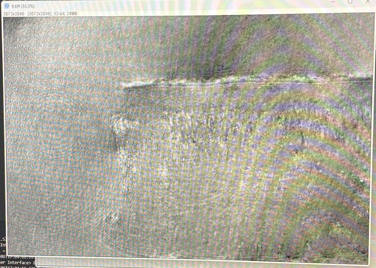
openUC2 Mach-Zender Interferometer
Tutorial: Mach-Zender Interferometer
Setup Arrangement for the Mach Zehnder Interferometer

Setup using an objective lens for microscopic imaging

Materials needed:
- Laser diode
- Hikrobot Camera (MV-CE060-10UC) with USB cable (Hikrobot Camera Software installation).
- Small stage with gear.
- Two kinematic mirrors (in cubes).
- Two beam splitters in cube.
- Sample holder (in cube).
- Two empty cubes.
- Base plates.
- Screen.
- Pinhole in cube.
- Screwdriver to adjust alignment (1,5x60)
- Two 100 mm converging lenses.
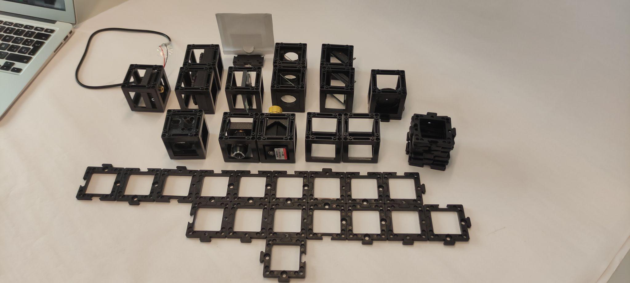
Instructions for assembling the Mach-Zender Interferometer:
Step 1: Build the base plate configuration
Build the base plate configuration as shown. Note: At this point the laser diode should be turned off the whole time. Don't look at the laser directly. Always use screens to look for the laser light.
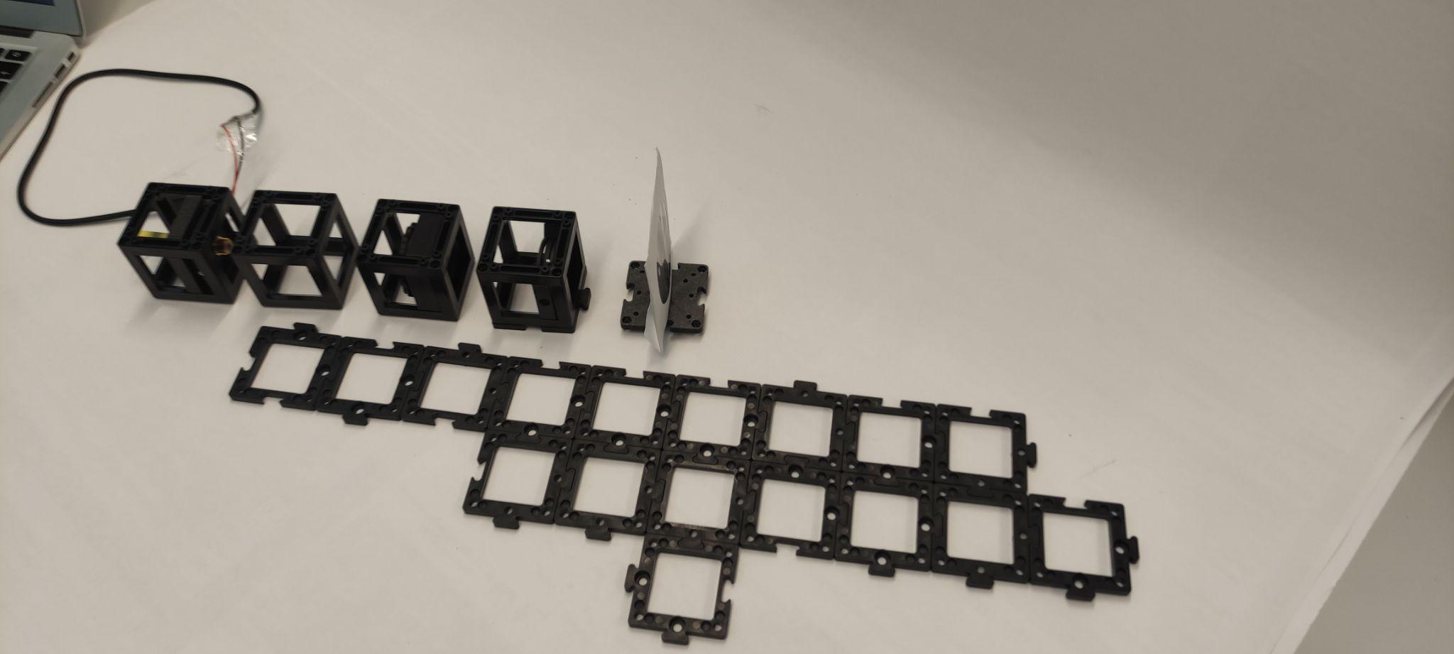
Step 2: Align the laser diode with the pinhole
Place the laser diode, an empty cube, and a 100 mm convergent lens in a straight line. Then, place the pinhole two cube units from the lens and place the screen after the pinhole. Turn the laser on and align it using by using the screws to center the beam with the pinhole.
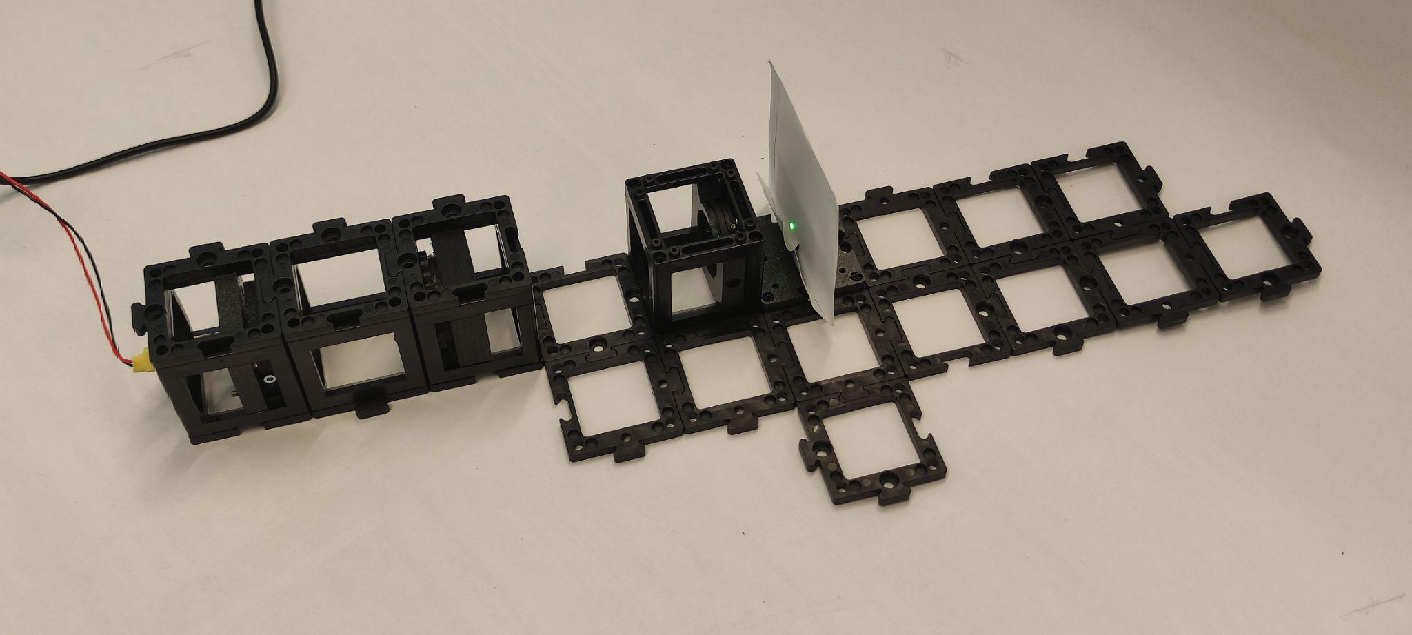
Step 3: Check beam collimation
Check if the beam is collimated by placing the screen at different distances. The beam diameter should stay relatively the same size. If it is not the same size, this means that the distance between the laser and the lens should be adjusted. Turn the laser off.
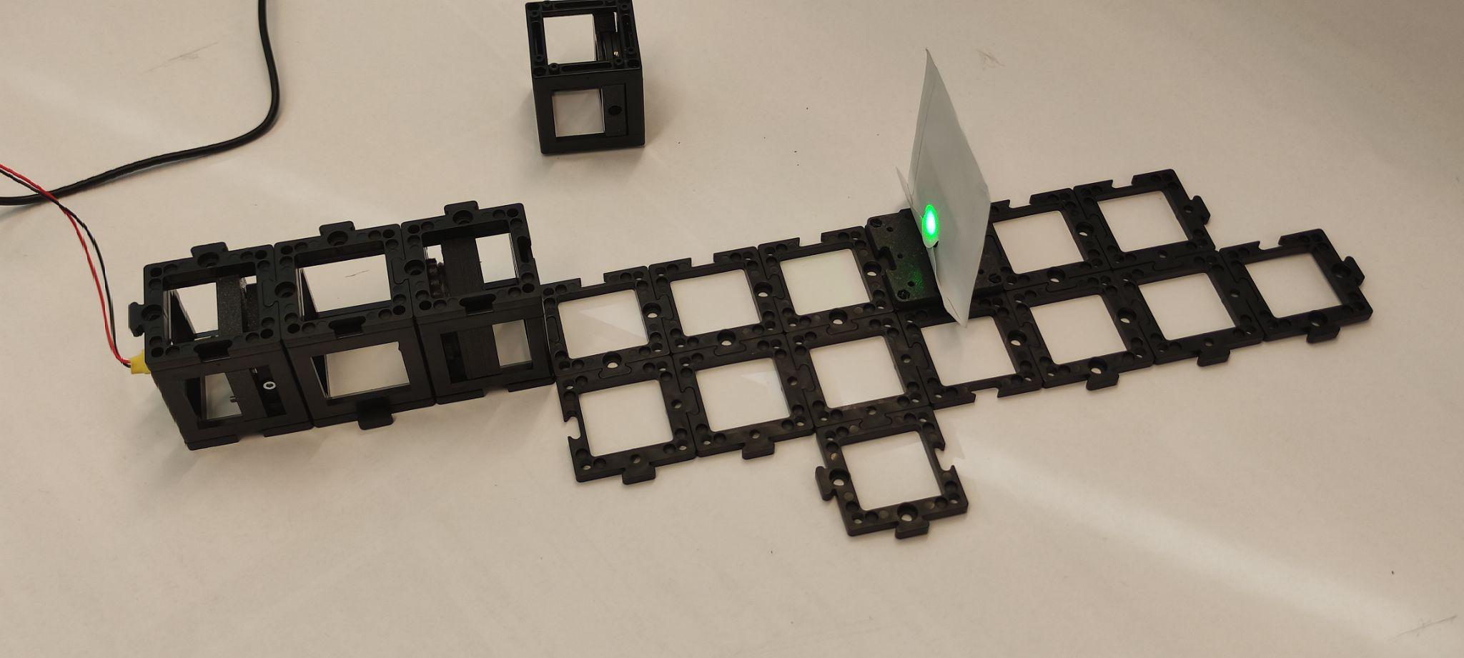
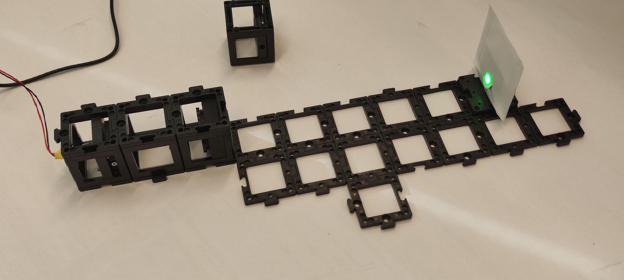
Step 4: Set up the beam splitter and mirror
Place the beam splitter and the kinematic mirror as shown. Place the pinhole two cube units away from the mirror and the screen behind it. Turn the laser on and align the kinematic mirror using the screws. Once it's done, turn the laser off.
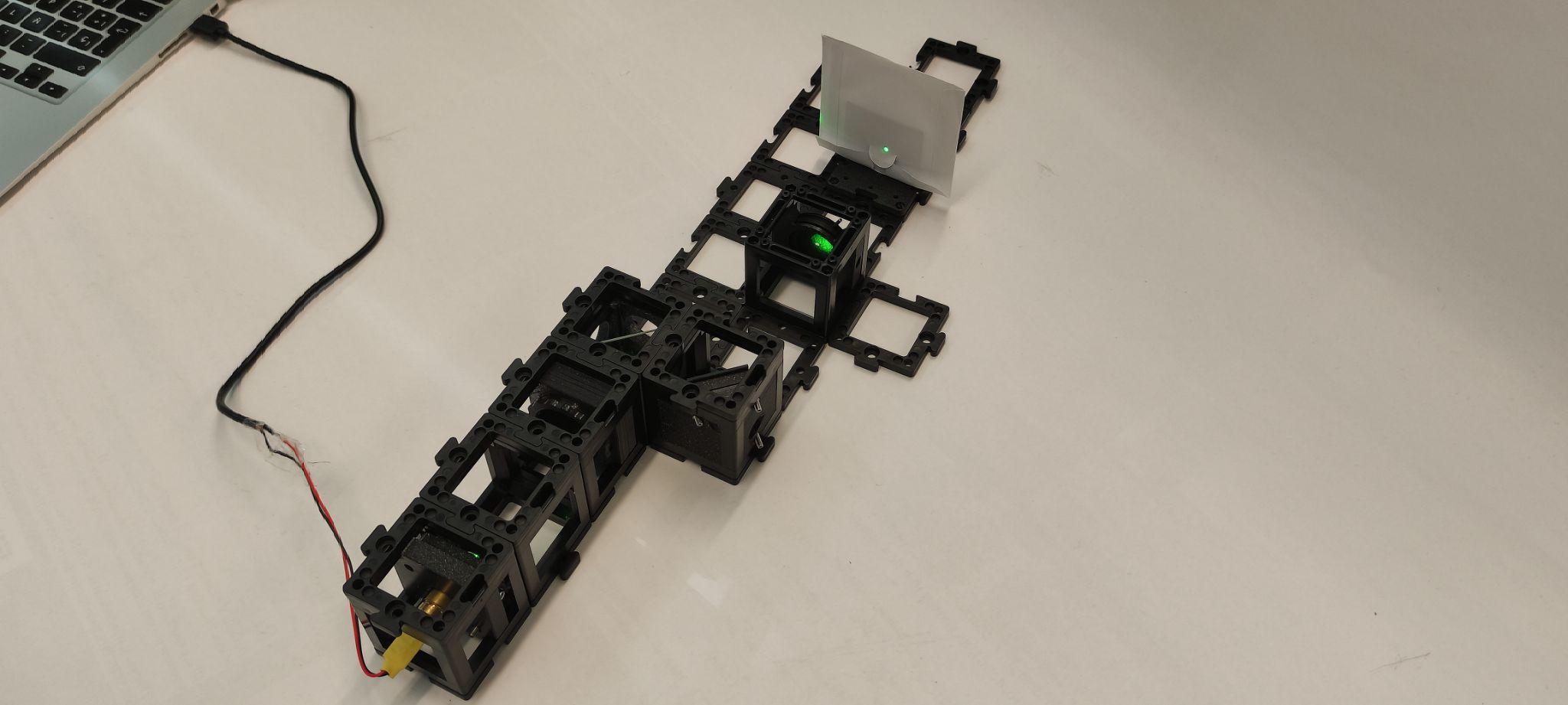
Step 5: Adjust the microscope objective and lens
Place the microscope objective, followed by an empty cube and the 100 mm lens. You should adjust the distance between the objective and the 100 mm lens so that the beam is collimated after going through both. Place the screen after the lens. Turn the laser on and check the collimation. Adjust the distance as necessary. Turn the laser off.
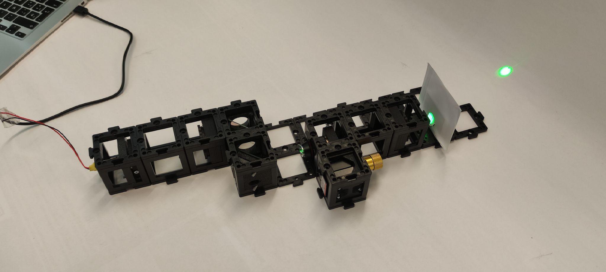
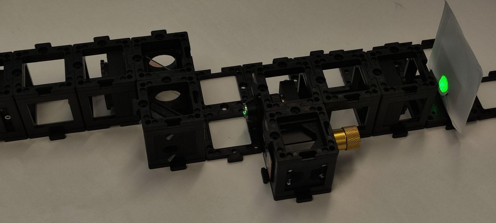
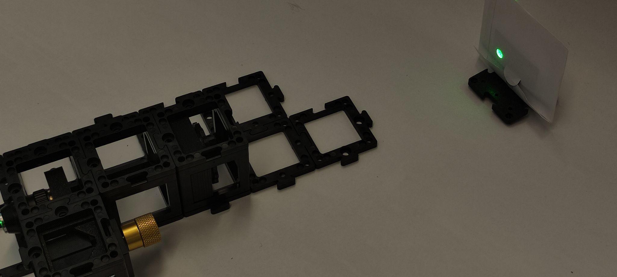
Step 6: Setup and alignment
Place the camera on the sample arm as shown. Put the screen on the other arm exit. Place the sample holder using one half of the cube at a time to not collide with the microscope objective.
Turn the laser on and use the screen to align both beams using the screws on the reference mirror.
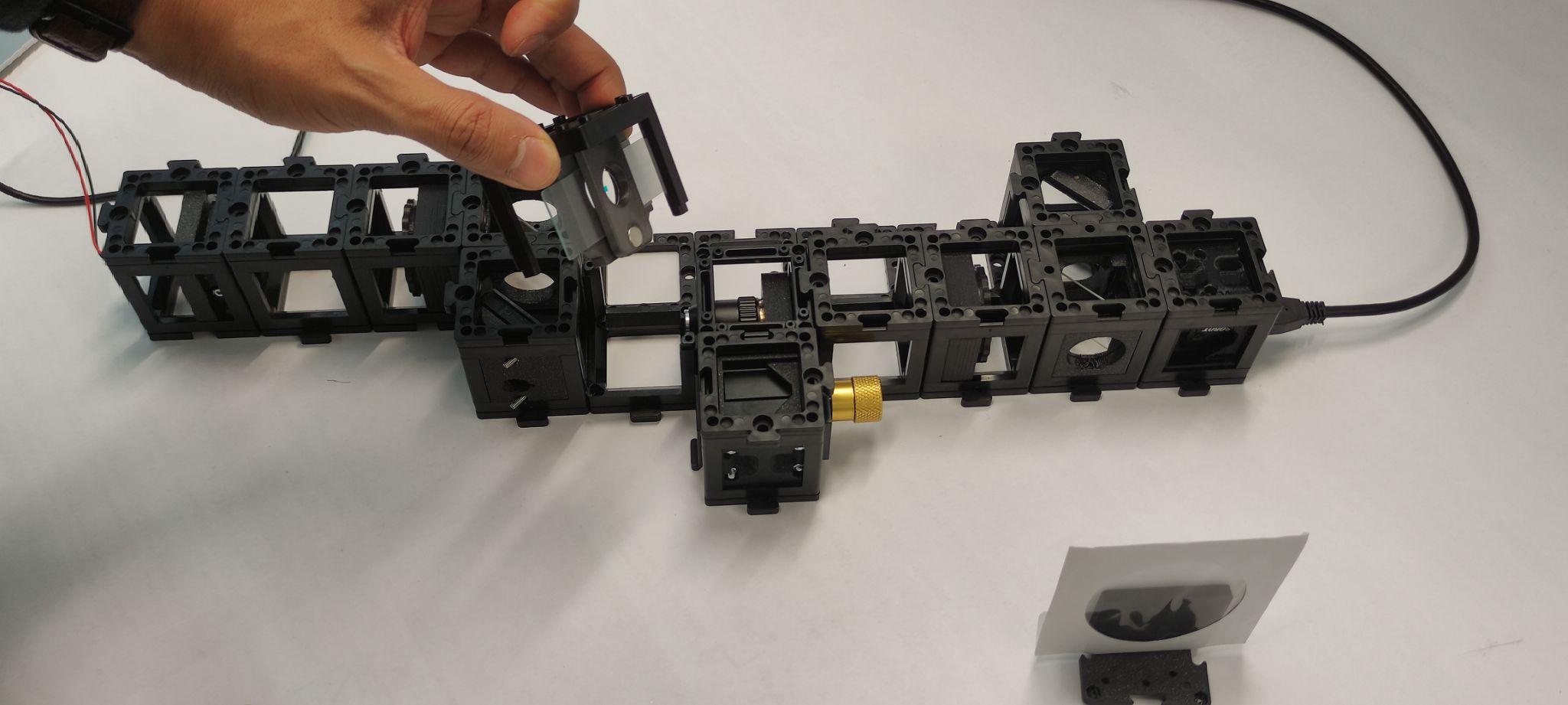
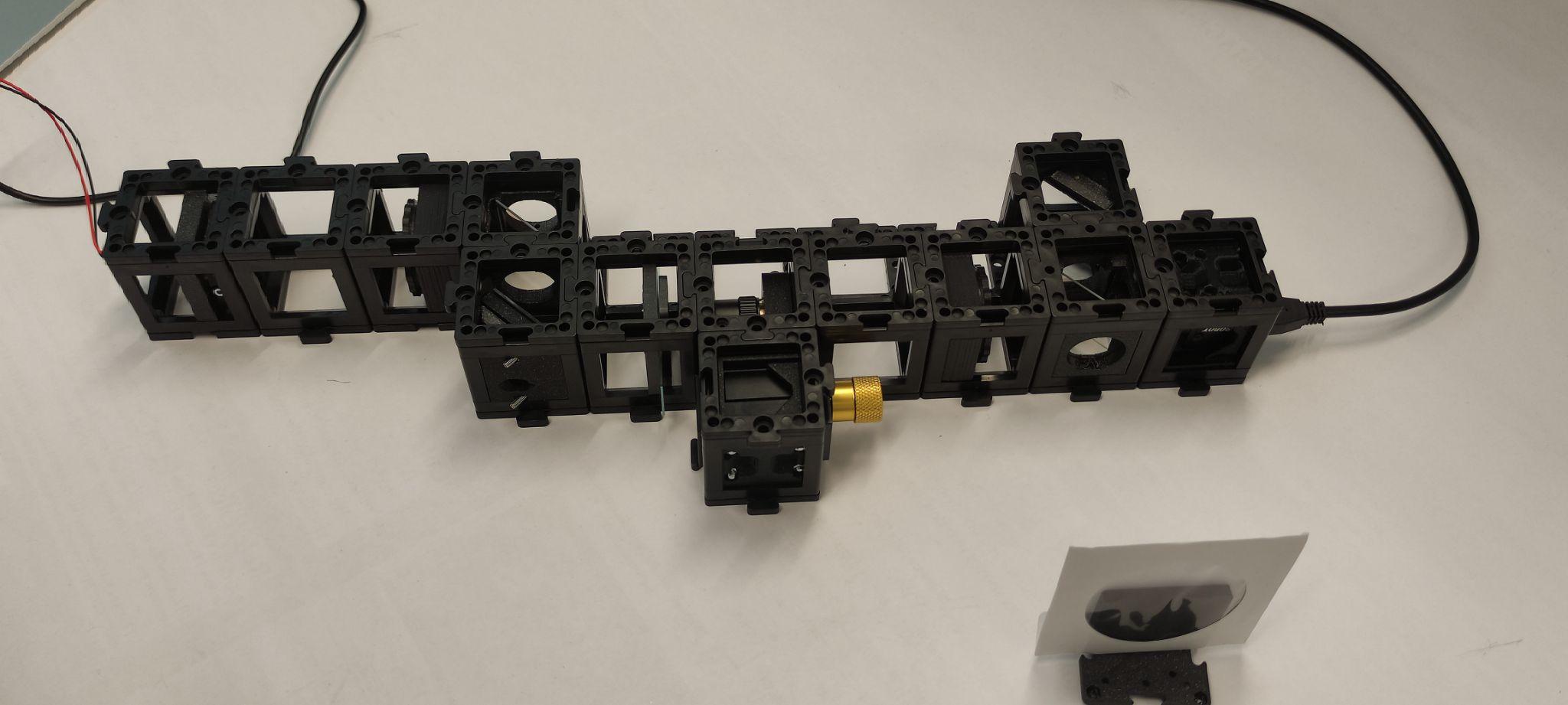
Step 7: Connect and adjust in the MVS app
Connect the camera to the computer and open the MVS app. Block the reference beam. Move the coverslide such that your sample enters the FoV (Field of View). Unblock the reference beam. Zoom into the image to distinguish the fringe pattern in the MVS camera display. Adjust the angles of the reference mirror using the screws to change the fringe pattern as shown.
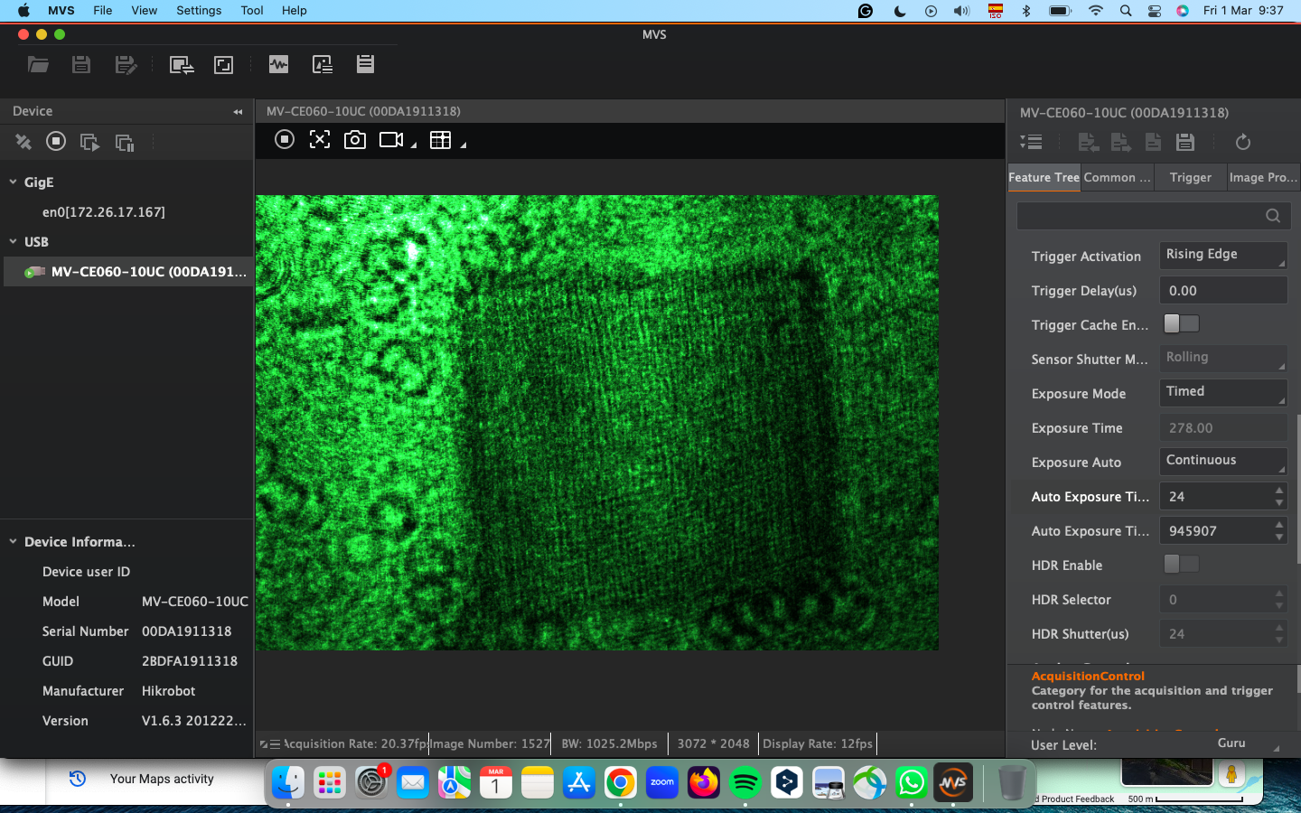
Step 7: Data processing
Process the data. Phase unwrapping possible.
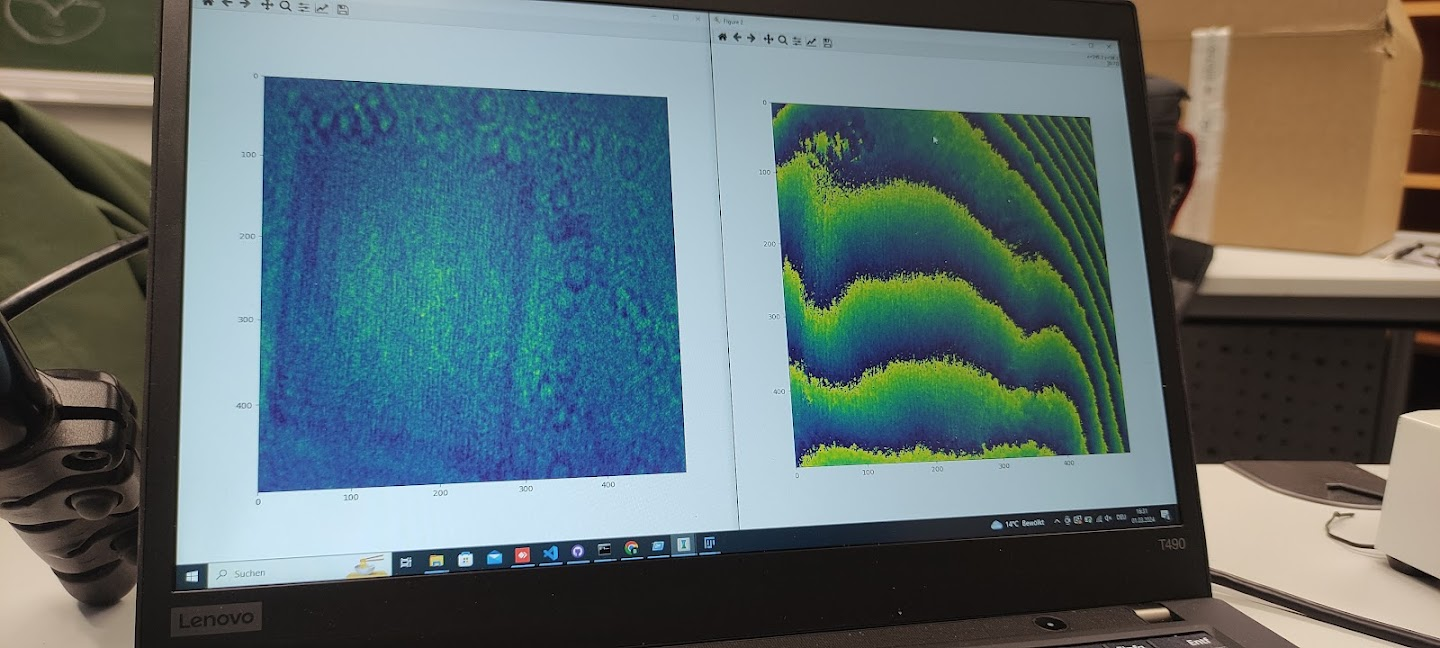
First Tests with Modifications to the Original Setup
Using Lei code, the need of a linear stage for the sample was identified. Adjusting the objective and tube lens enhances the interference, making it crucial to use the ImSwitch interface to see the FFT in real time and optimize. The final goal is to move the position of the first order interference to use Lei algorithm (or some Phase unwrapping algorithm) to retrieve the Phase. To achieve this, two images need to be acquired: a sample image and a background image (without a cover slide or a slide region with no specimen).
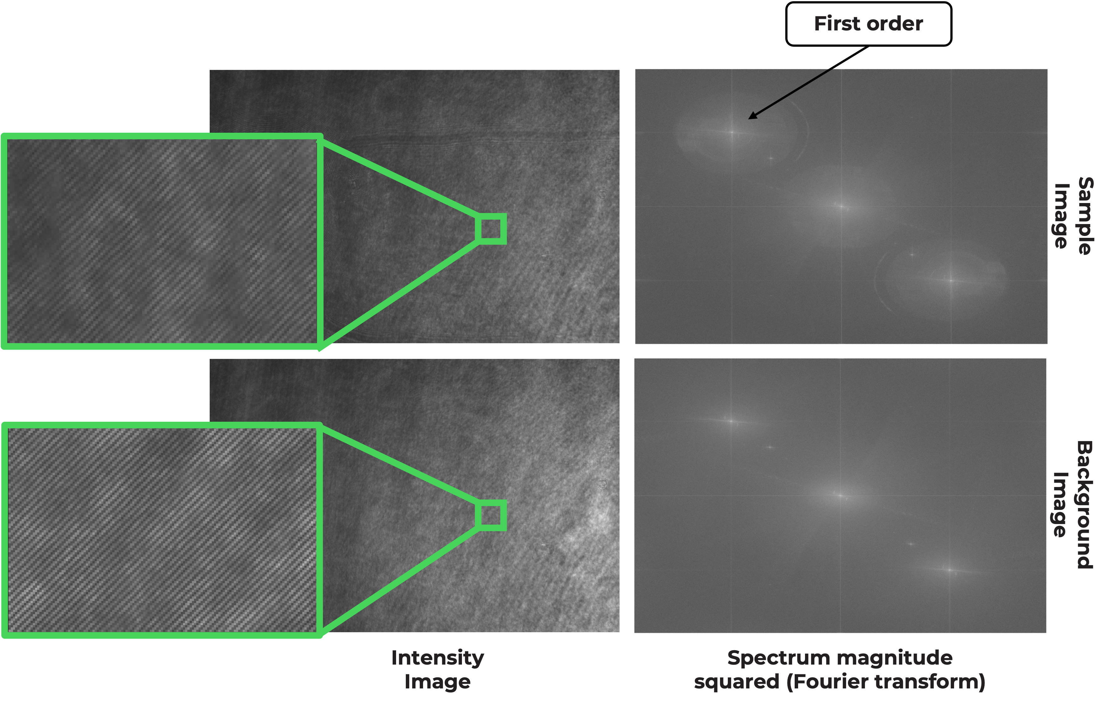
Result of Phase Unwrapping
