Assemble the XYZ Microscope
Bill of Material
This is exported from Inventor
Assembly Procedure
Preparing the XY Stage
A first step is to prepare the XY stage such that it adapts the linear motors.
TODO:
- have sketch for drilling holes
Tools
Find the necessary tools to get rid of the necessary parts of the stage:
- Philips screwdriver at various sizes (small, coarse)
- slotted screwdriver at various sizes (small, coarse)
- Pliers "Kneifzange"

Steps
Please collect all parts in the bag that comes with the XY stage. First step: Remove ALL the screws on the up-facing surce (mostly cross)
Get rid of the sample clamps using the Philips 1 screwdriver (cross)
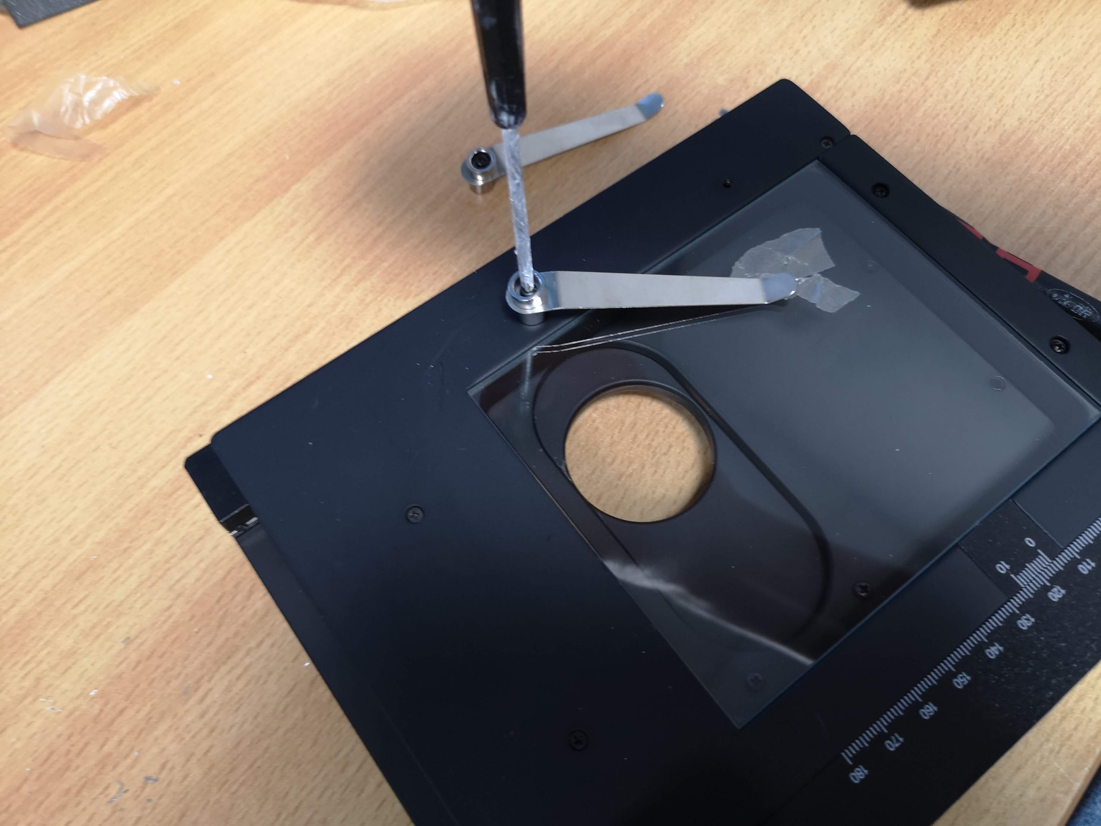
Remove the metal bars that frame the glass plate

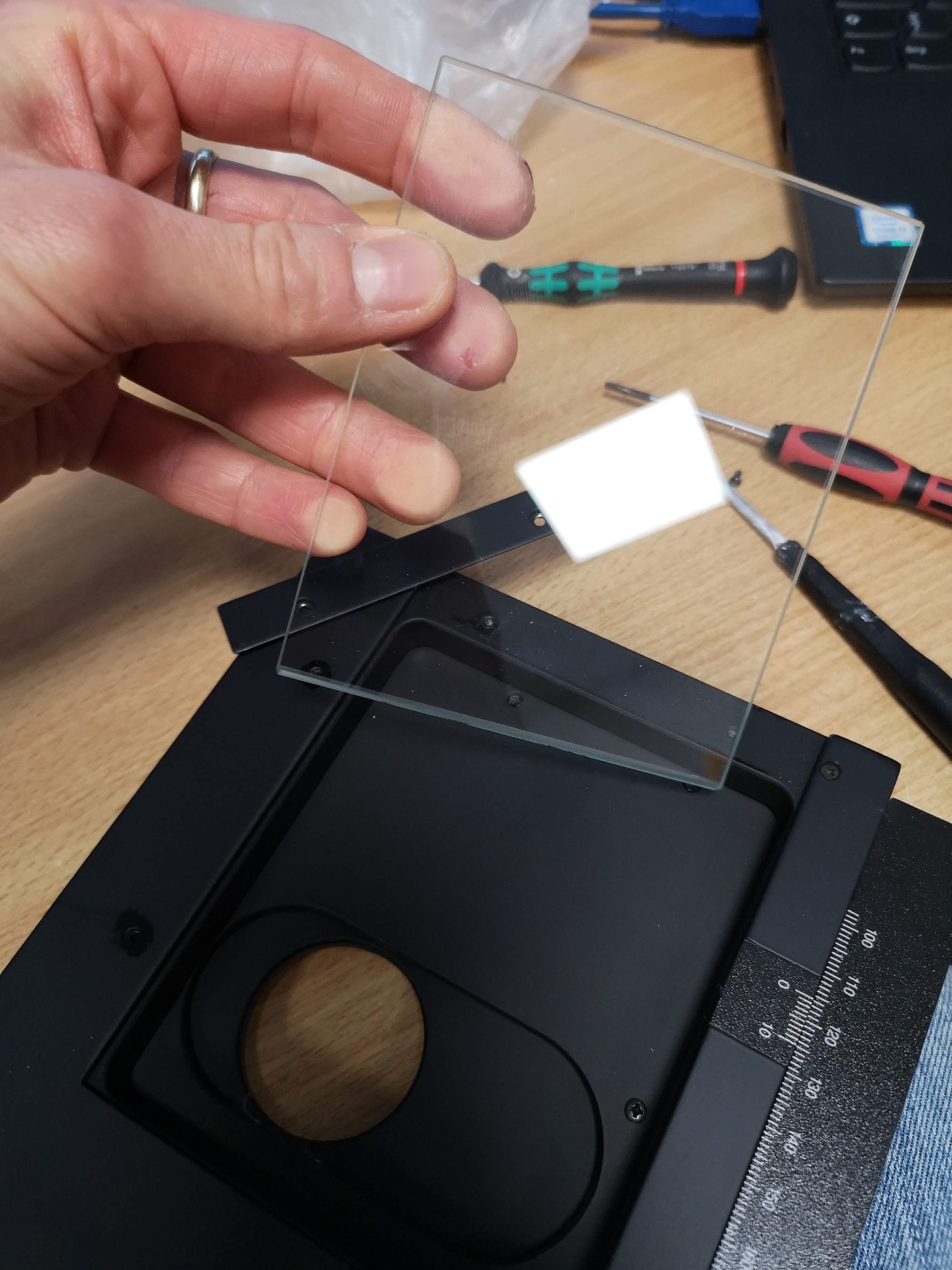
Remove the glass plate - don't cut yourself!
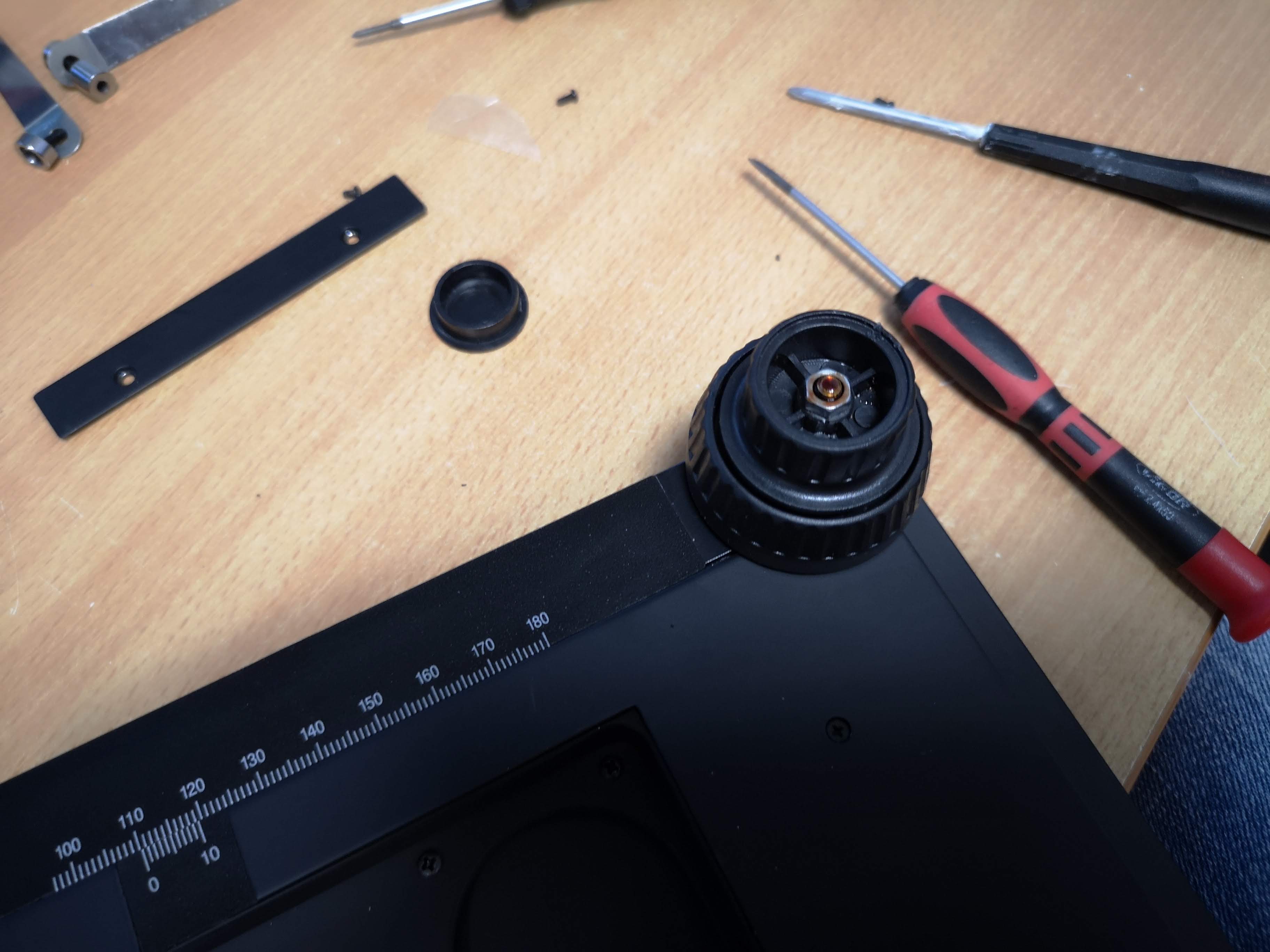
Take the slotted screwdriver (small) and remove the cap of the knob (there is a hole, insert it and remove the plastic piece)

You end up with this result:
Take the same slotted screw driver and remove the stickers that indicate the ruler signs
The remaining residuals can be ignored.
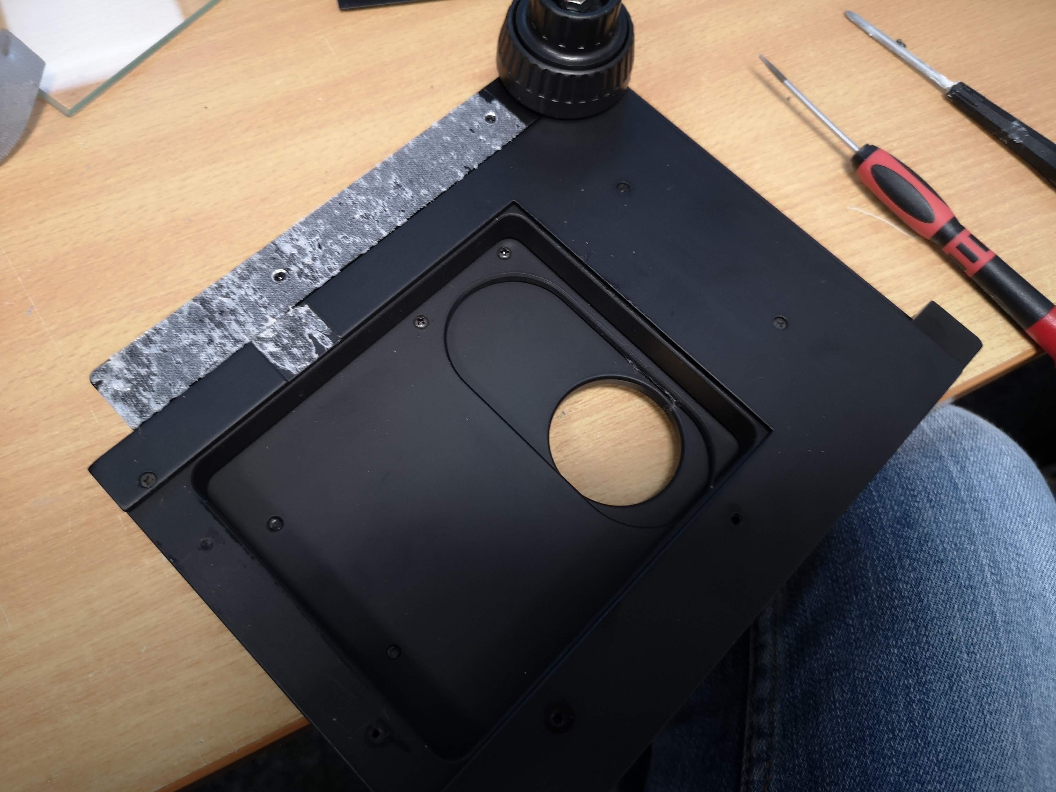
Take the small Philips (PH-1) and remove all screws on the xy deck

Remove the metal plate from the deck:

Take the 7mm nut and the ratchet to remove the M4 nut:

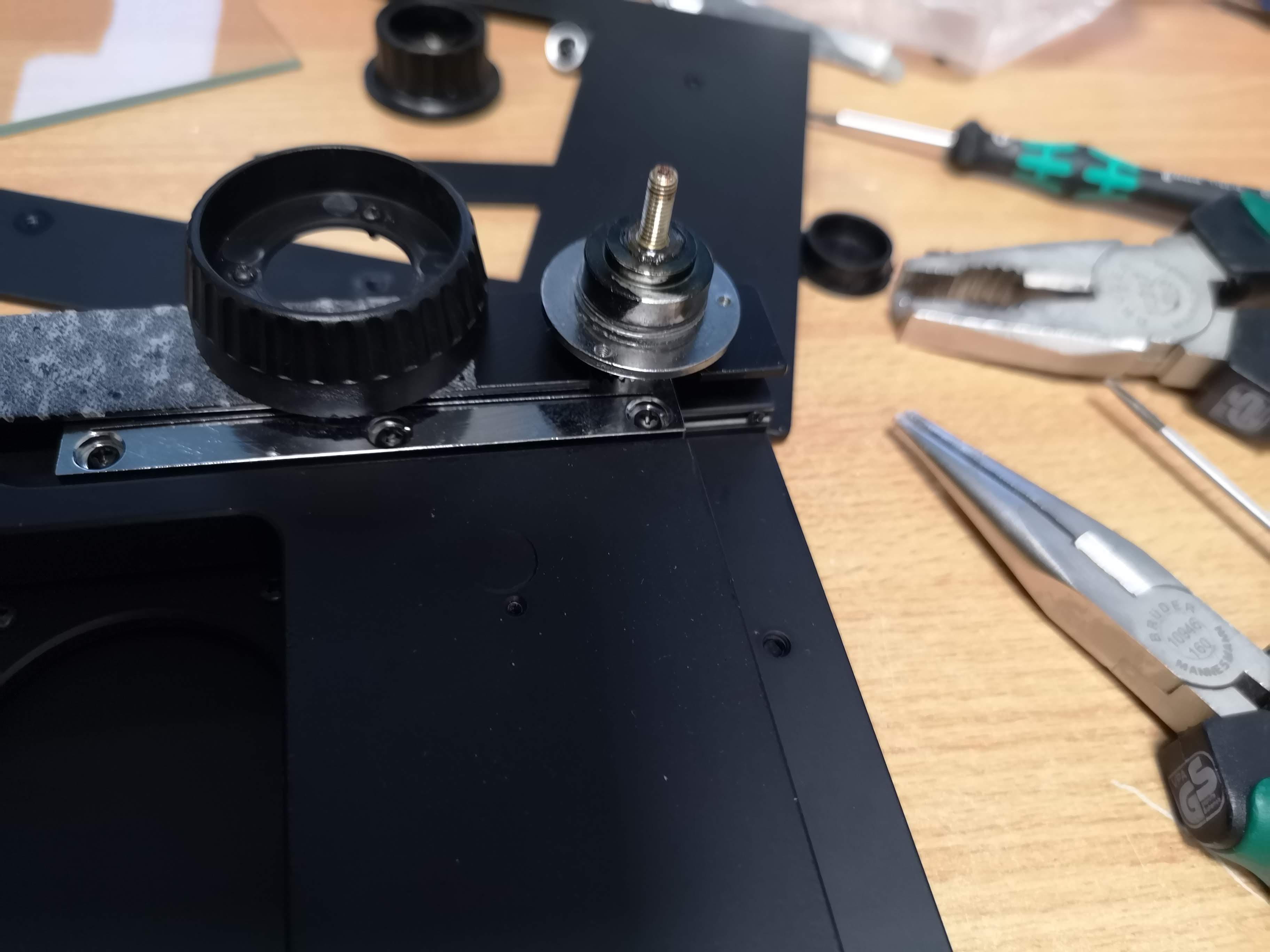
Remove the cap/knob by untwisting it counterclockwise:

Unscrew the small screws (3x) that hold the lower knob using the Philips (PH1)
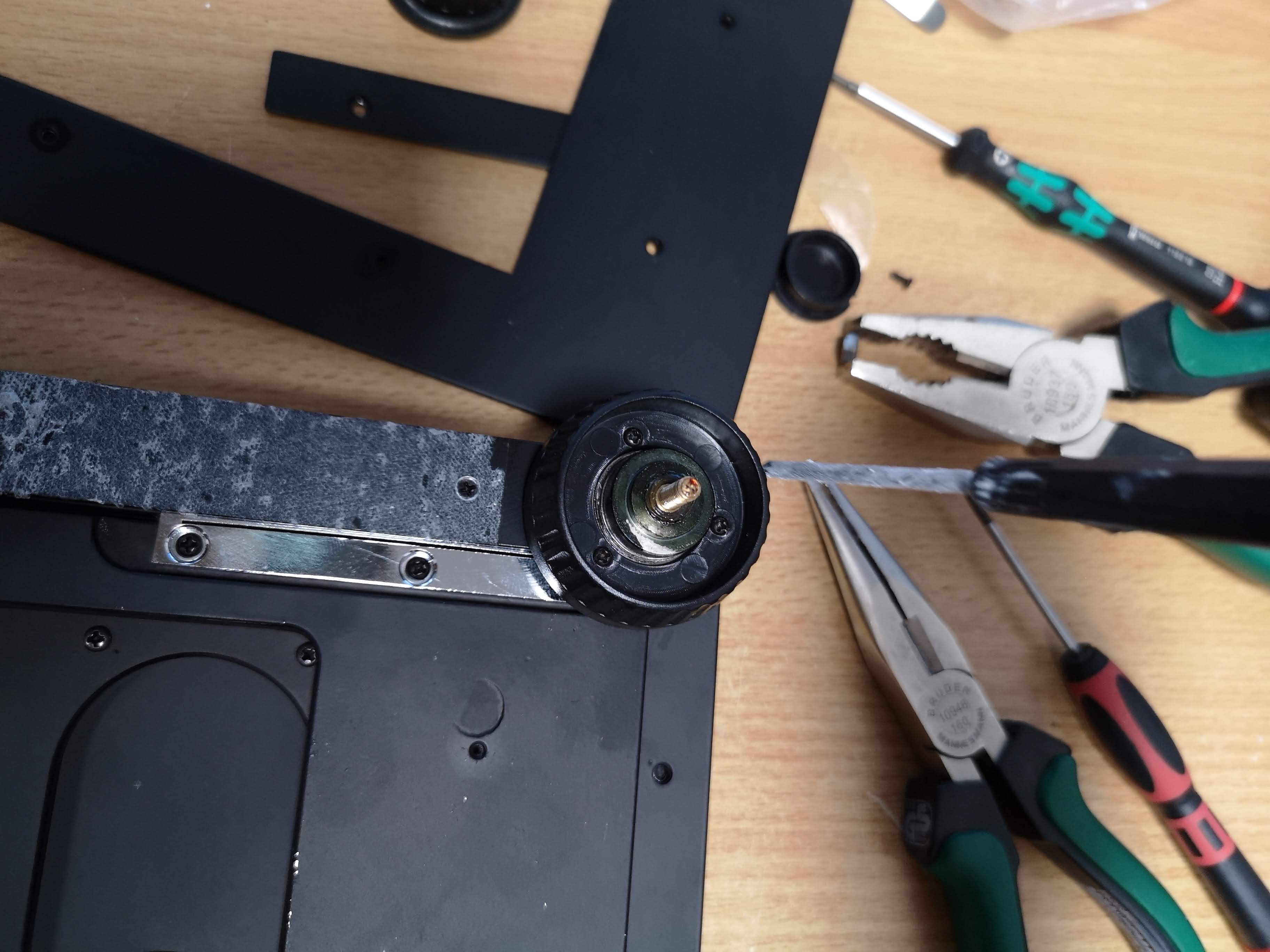
Remove the lower hand knob:
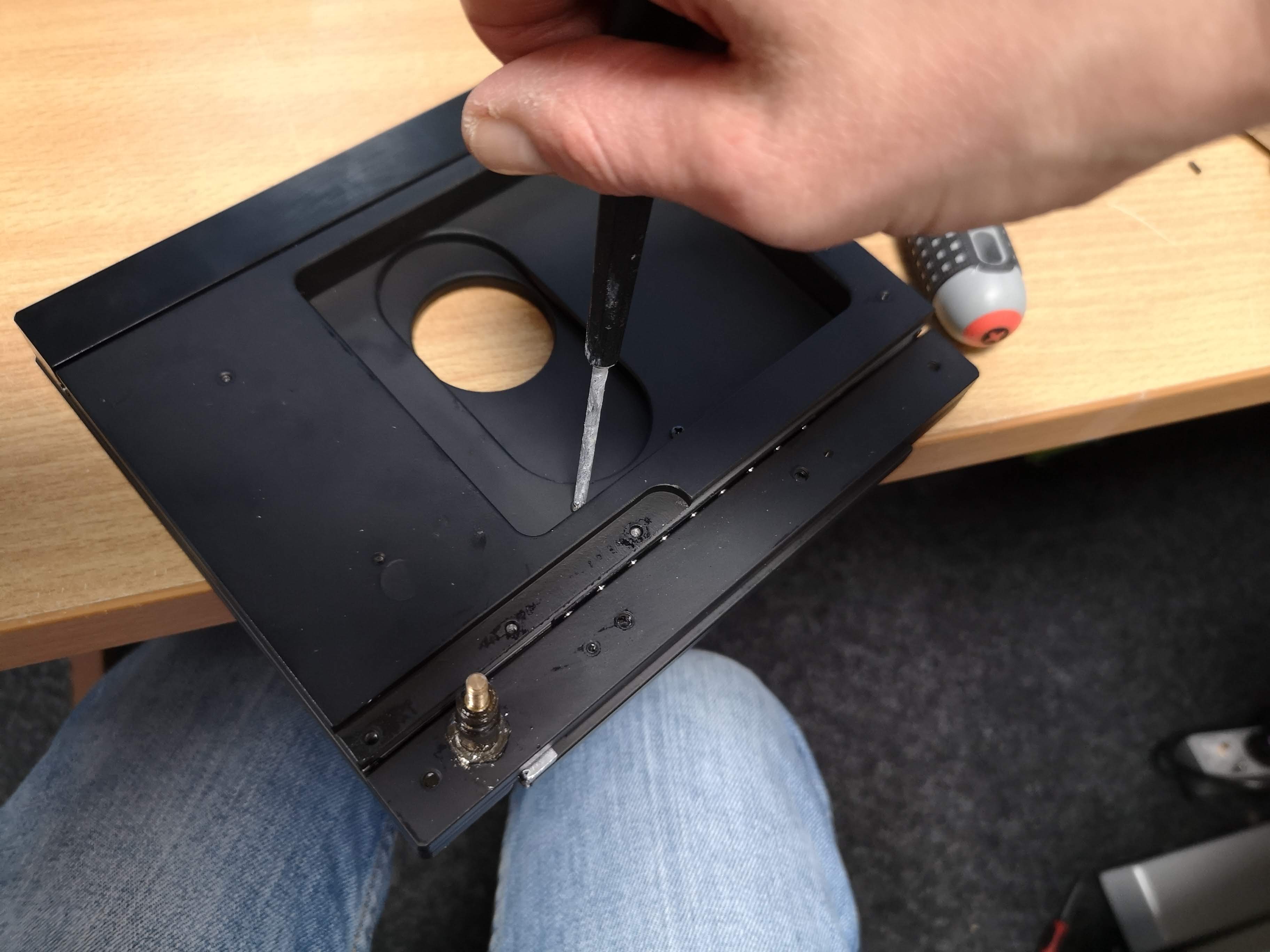
Turn over the stage
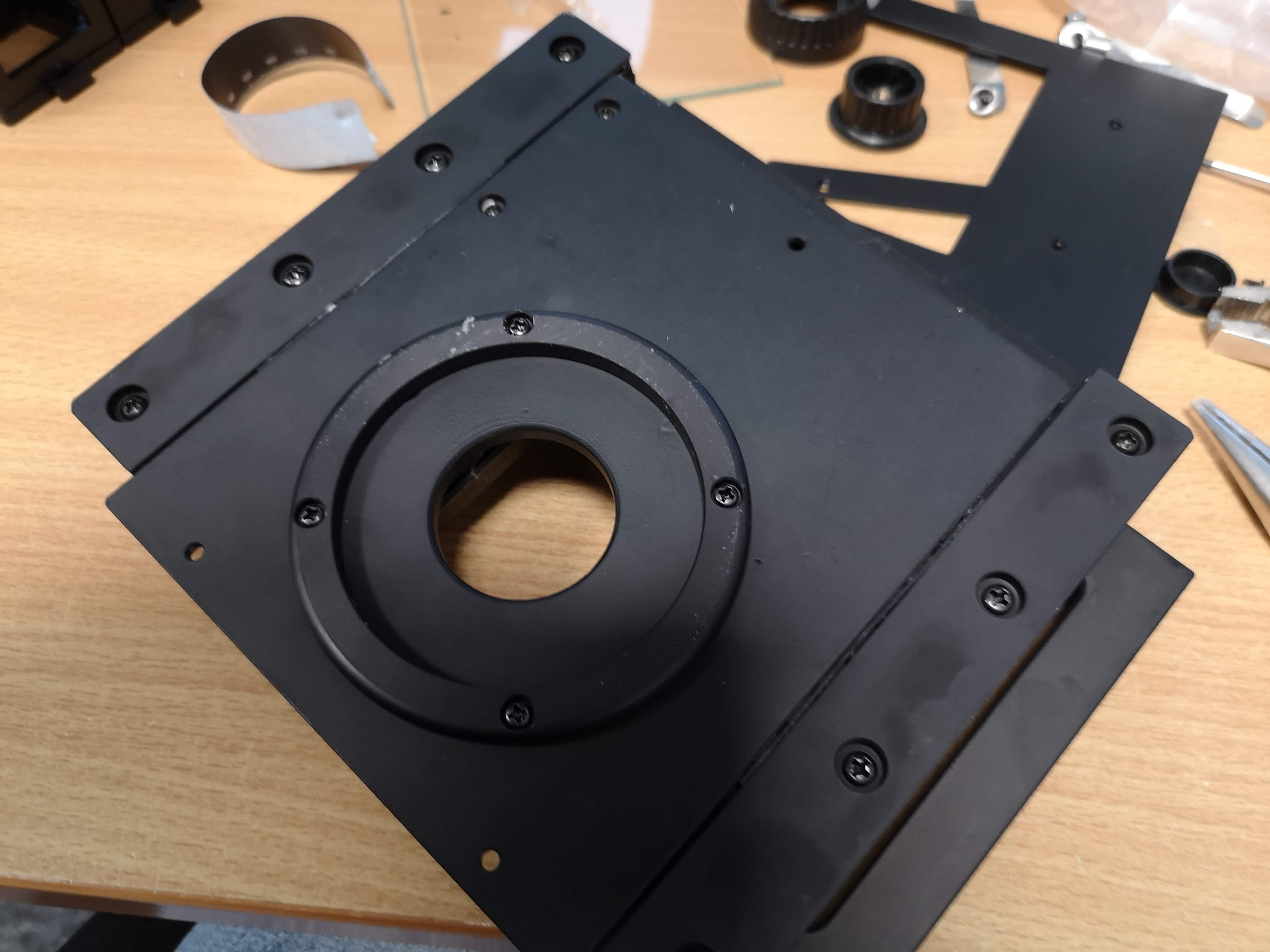
Remove the larger cross-headed screws with the larger Philips (PH2) from the mounting ring:

Remove the ring

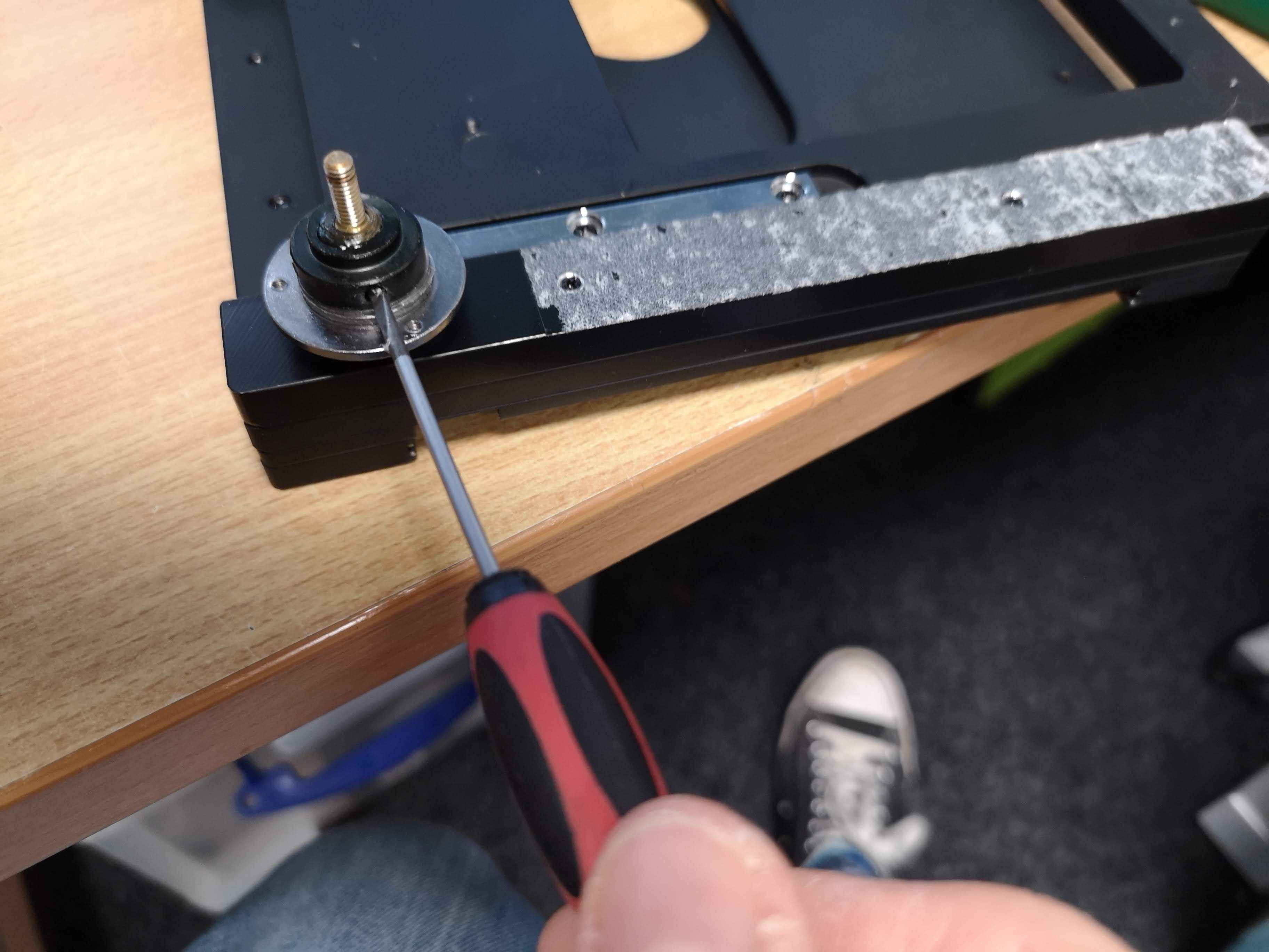
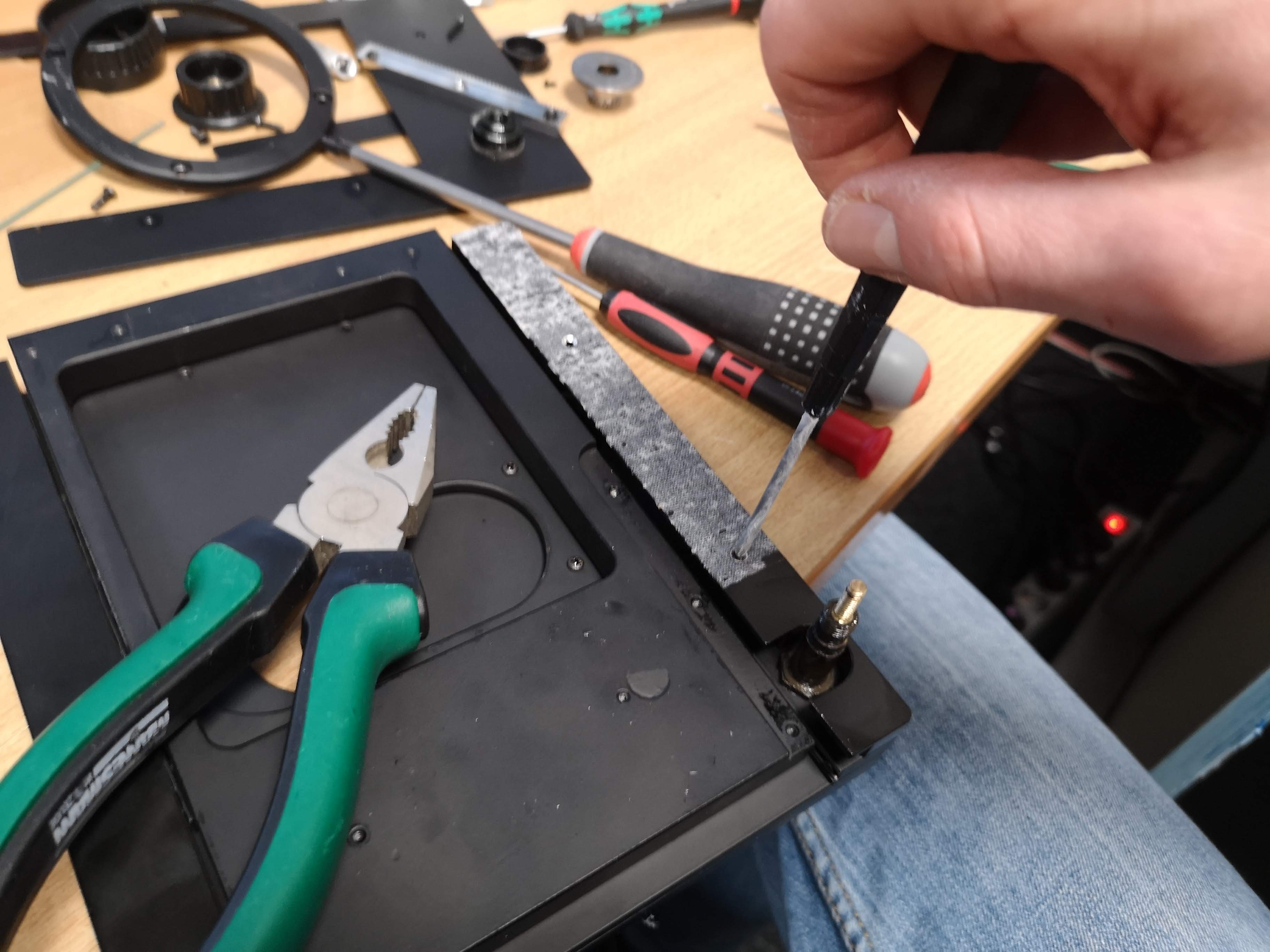
Turn over the stage again: Use the slotted screwdriver (2mm) to get rid of the screws (2x) in the lower knob (setscrews)
Remove all screws of the linear rack (linear gear) using Philips (PH1)

Remove the metal part:
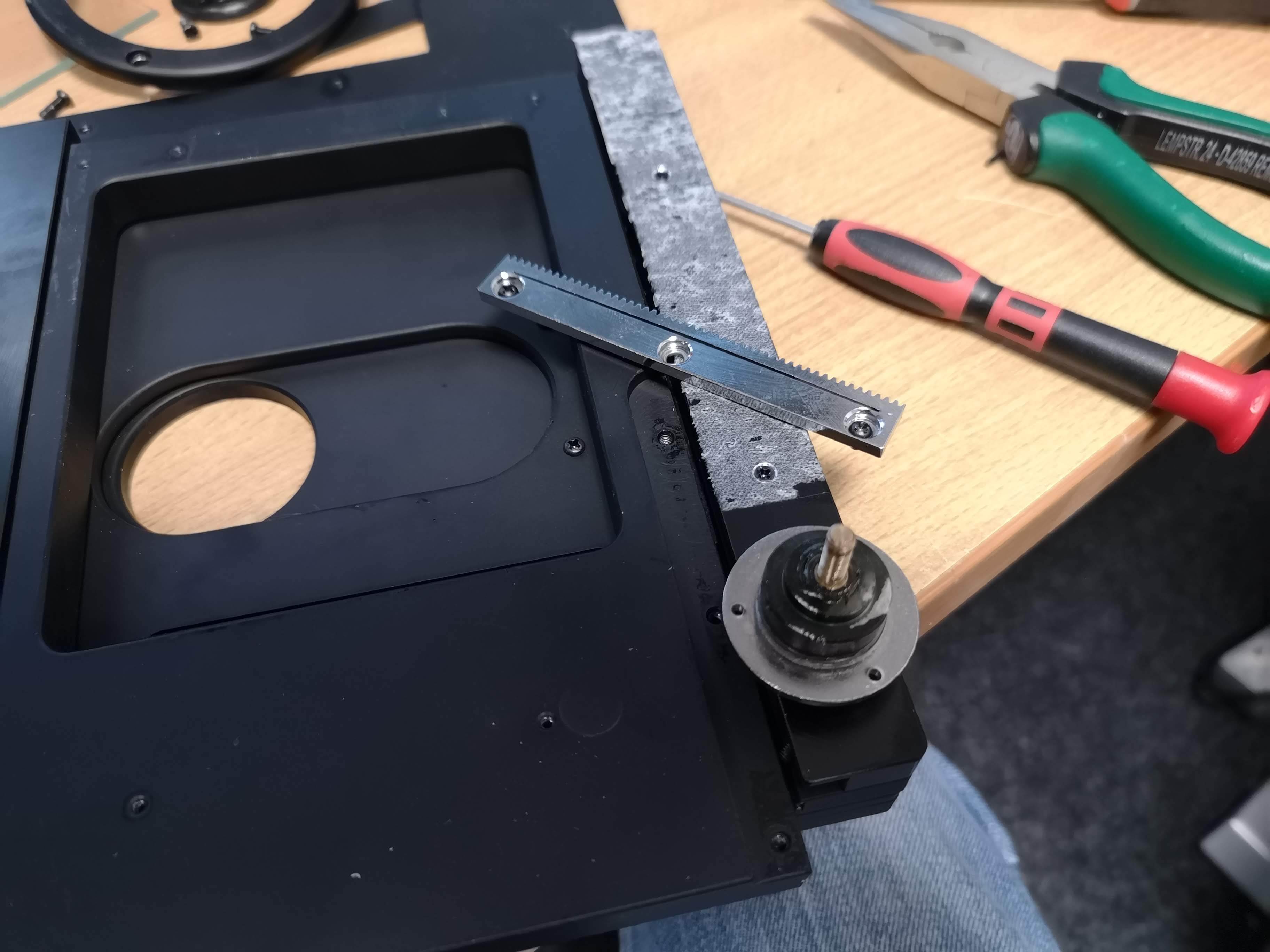
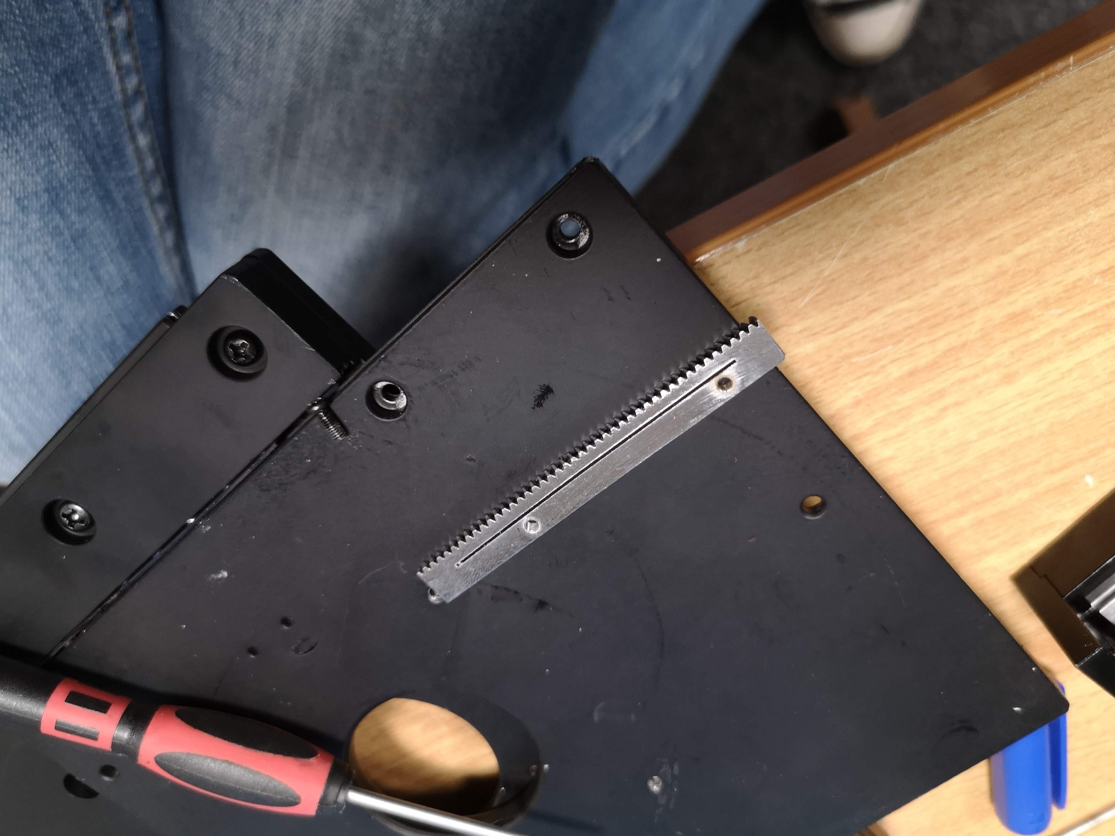
Same with the gear on the lower end
Remove the part:
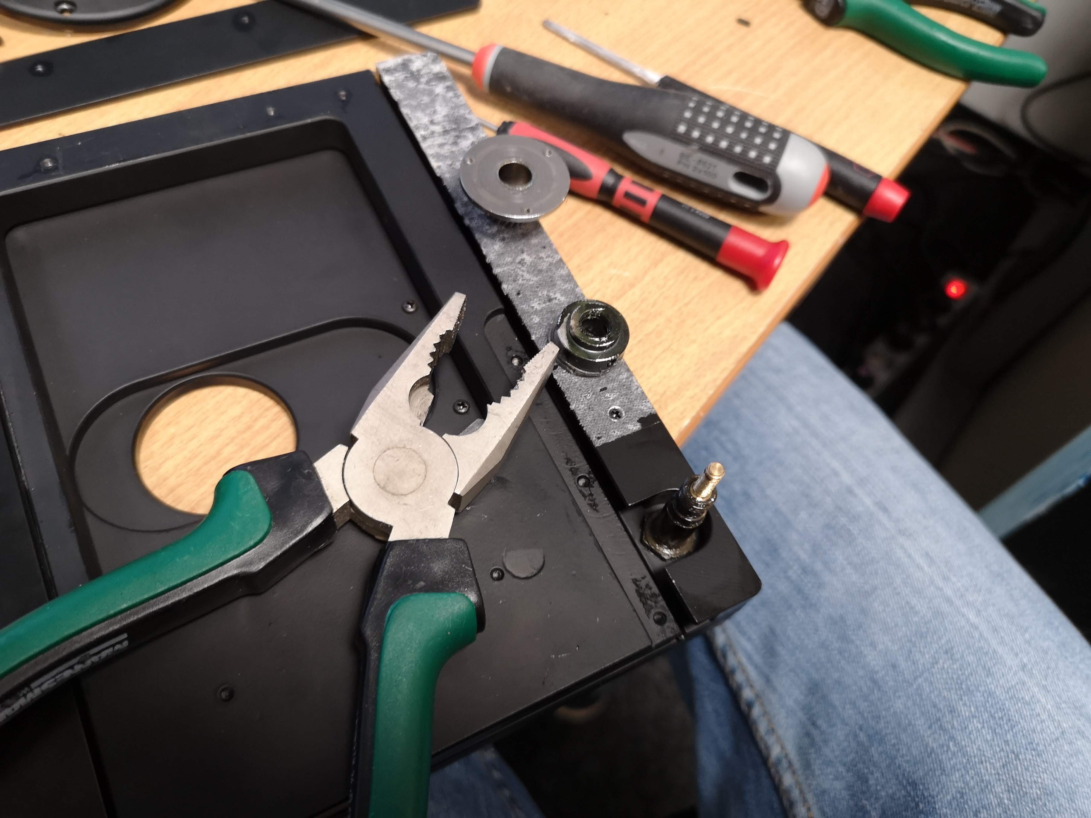
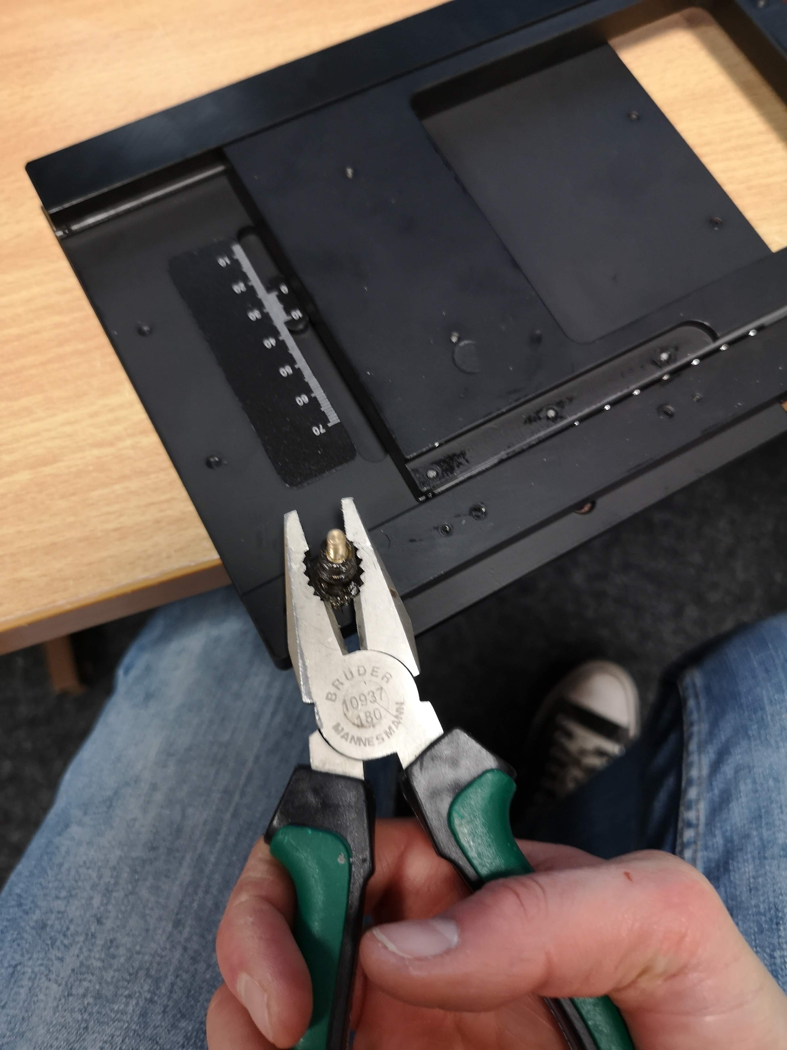
Unscrew the special-shaped nut. Attention: this holds lubricon, make sure you cover your fingers. Use papertowels to cover the part / your fingers.

Eventually take pliers to release the nut
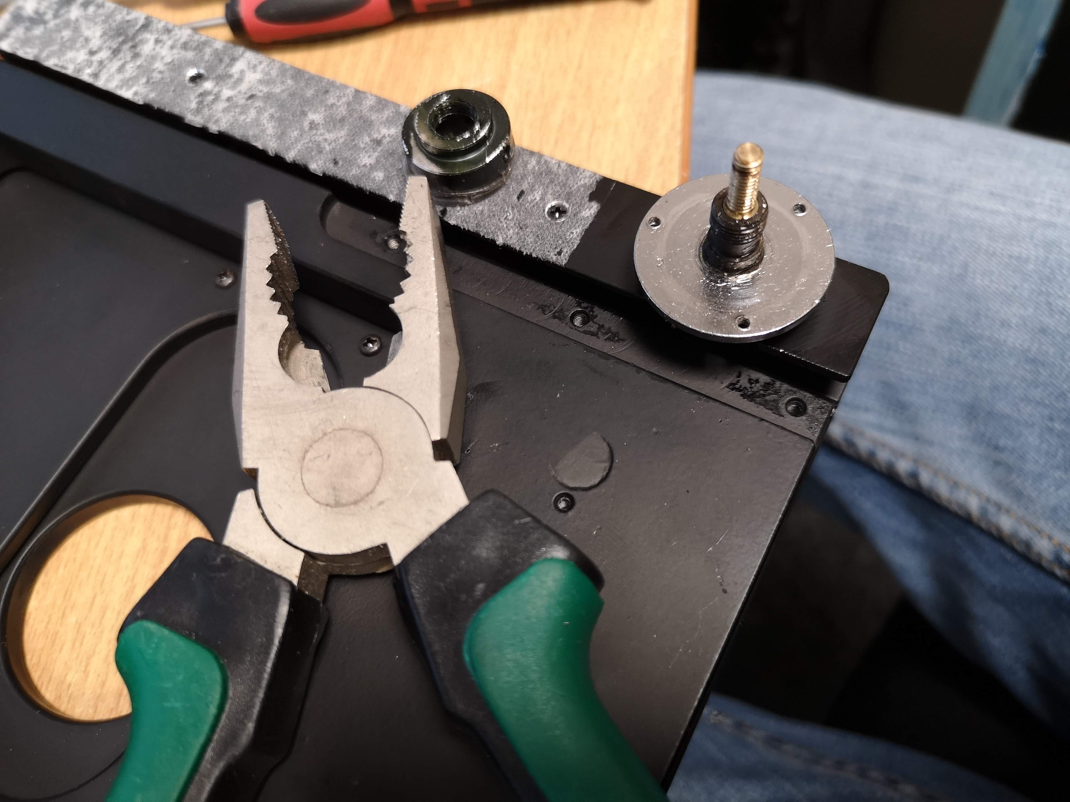
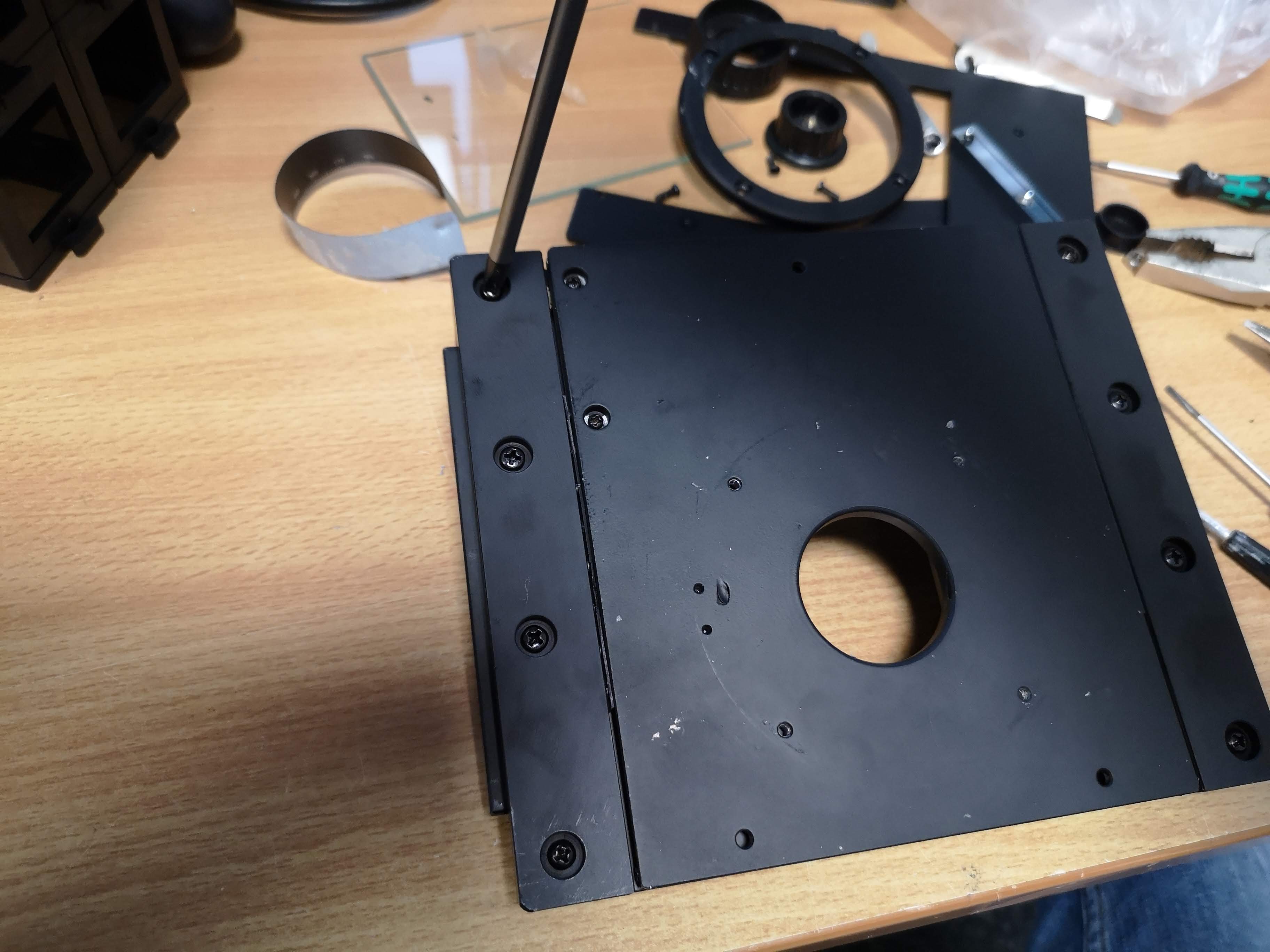
Remove the round metal plate by pulling it up (use paper towels!!)
Use the small Philips and remove the screws along the side and remove the metal part
Remove the screws inside the assembly in order to enlarge the travel range (PH1)
Take the wrench (12mm) and loosen the special-shaped screw assembly. Hold the lower nut and unscrew it counter-clockwise. Fully remove the screw using the papertowel by hand - all the way off.
It's not 100% straight forward, but it'll work out:

Tidy up the workplace:

Add drill holes to the XY Stage assembly
For this we will have a template that indicate all holes and their sizes soon! For now we will add the parts manually as shown below:
Tools
- Bosch Ständerbohrmaschine WPD40
- Drills: 2.8mm
- Drills: 4.7mm
- Tap: M3
- Tap: 4
- openUC2 drill template
- pen
Parts
- prepared xy stage
- NEMA12 100mm linear stage
- NEMA12 150mm linear stage
Steps
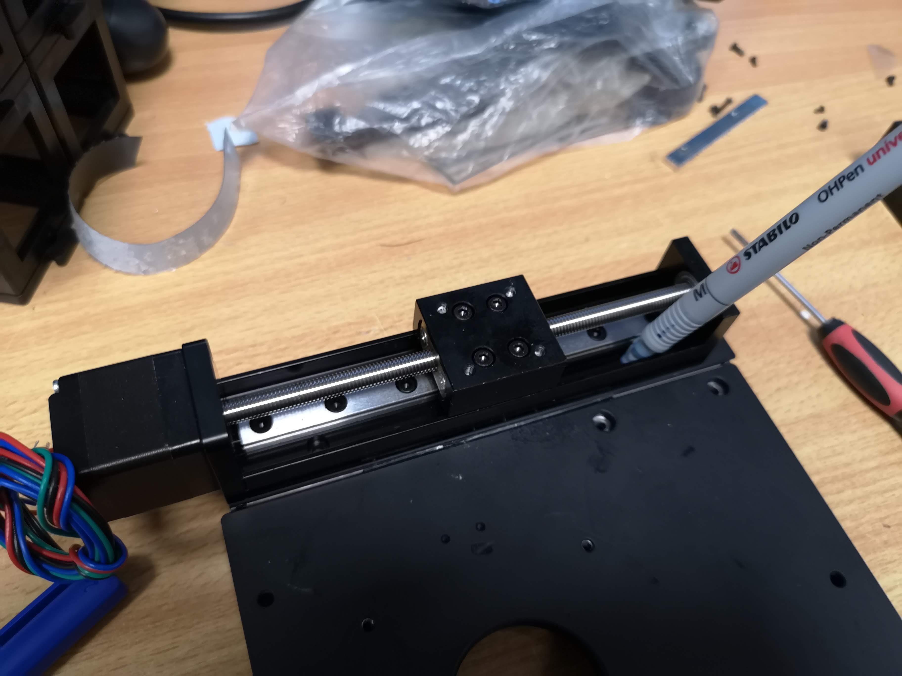
Take the 150mm stage and hold it on the plate as shown in the photo. Mark the holes that will mount the stage on the xy plate_
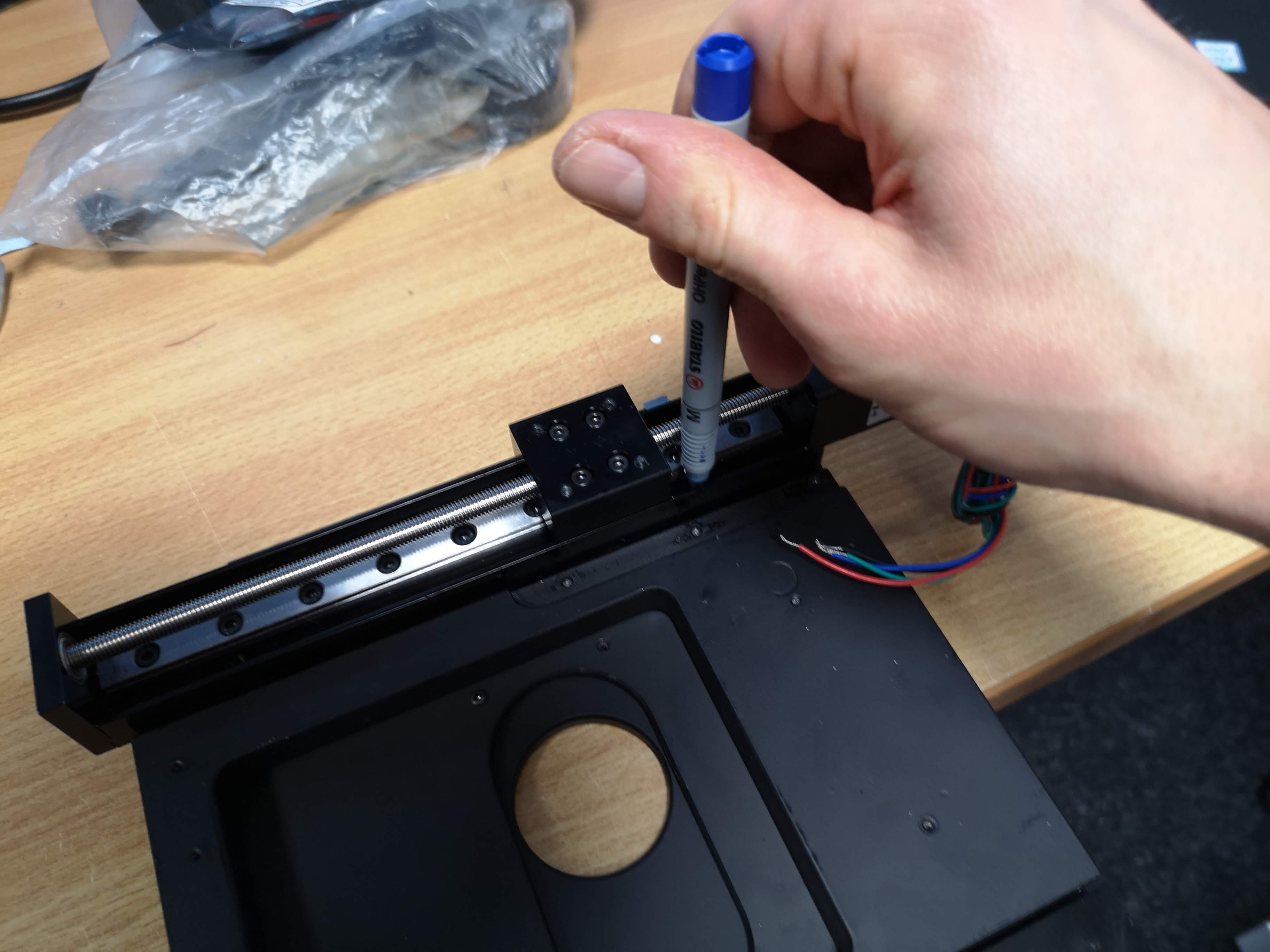
Same for the other (100mm) linear stage:
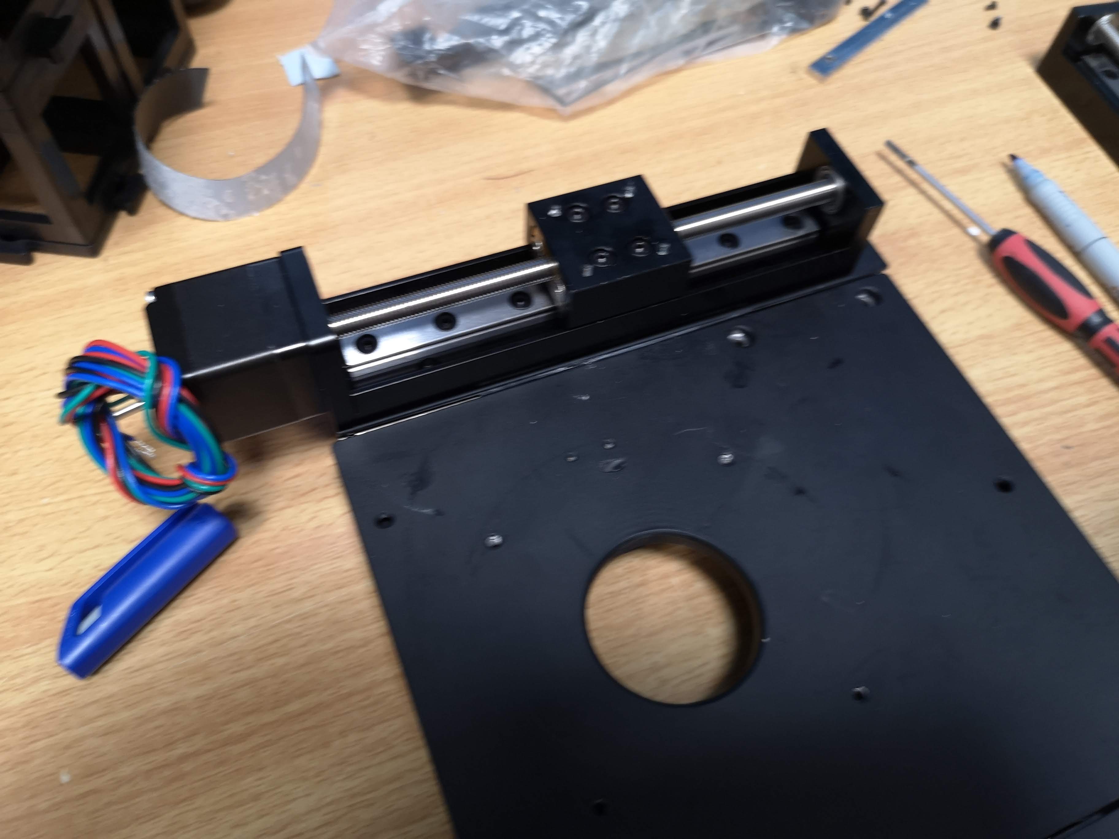
Add markers for the positioning on the xy stage
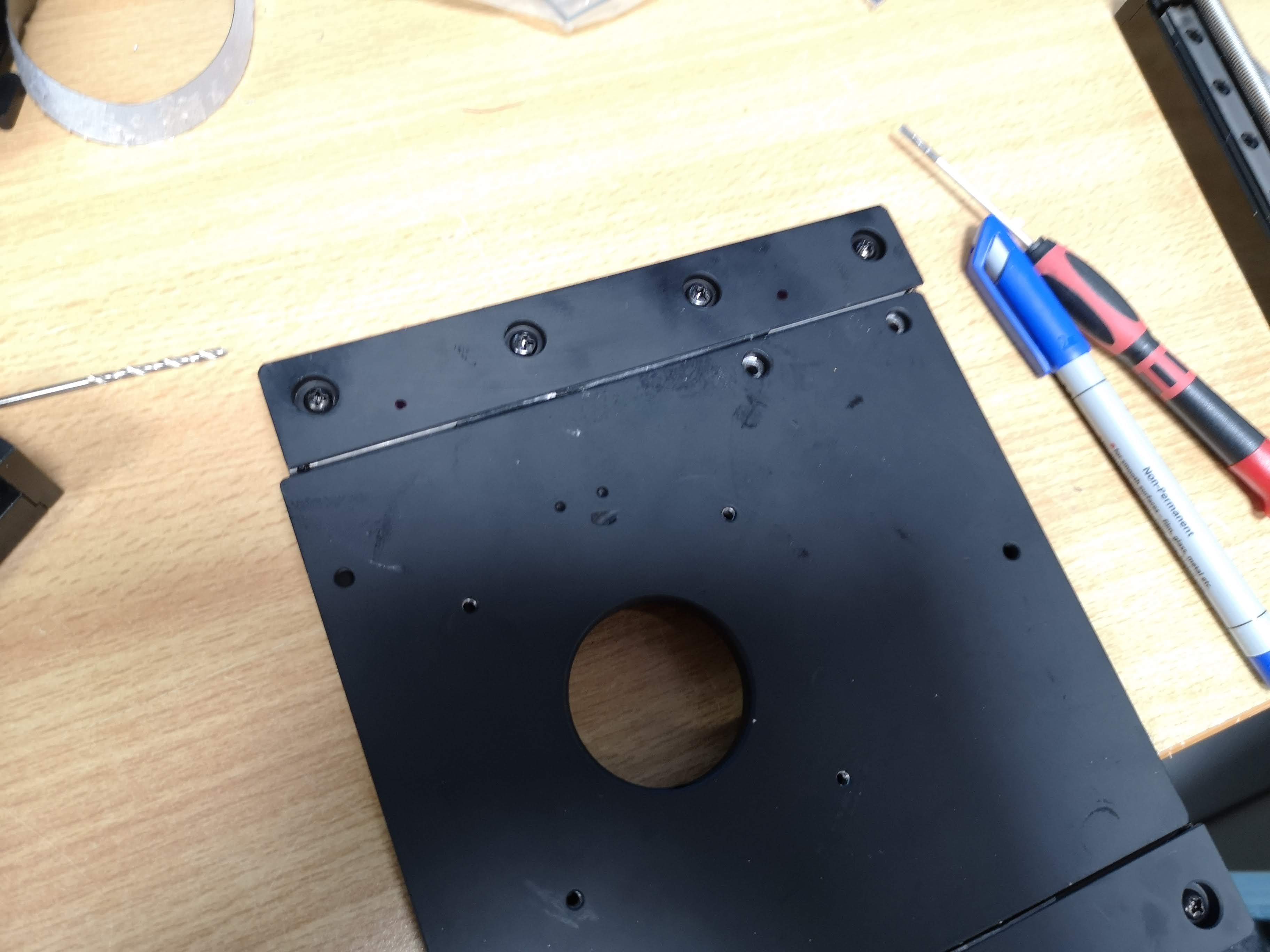
Quick check:
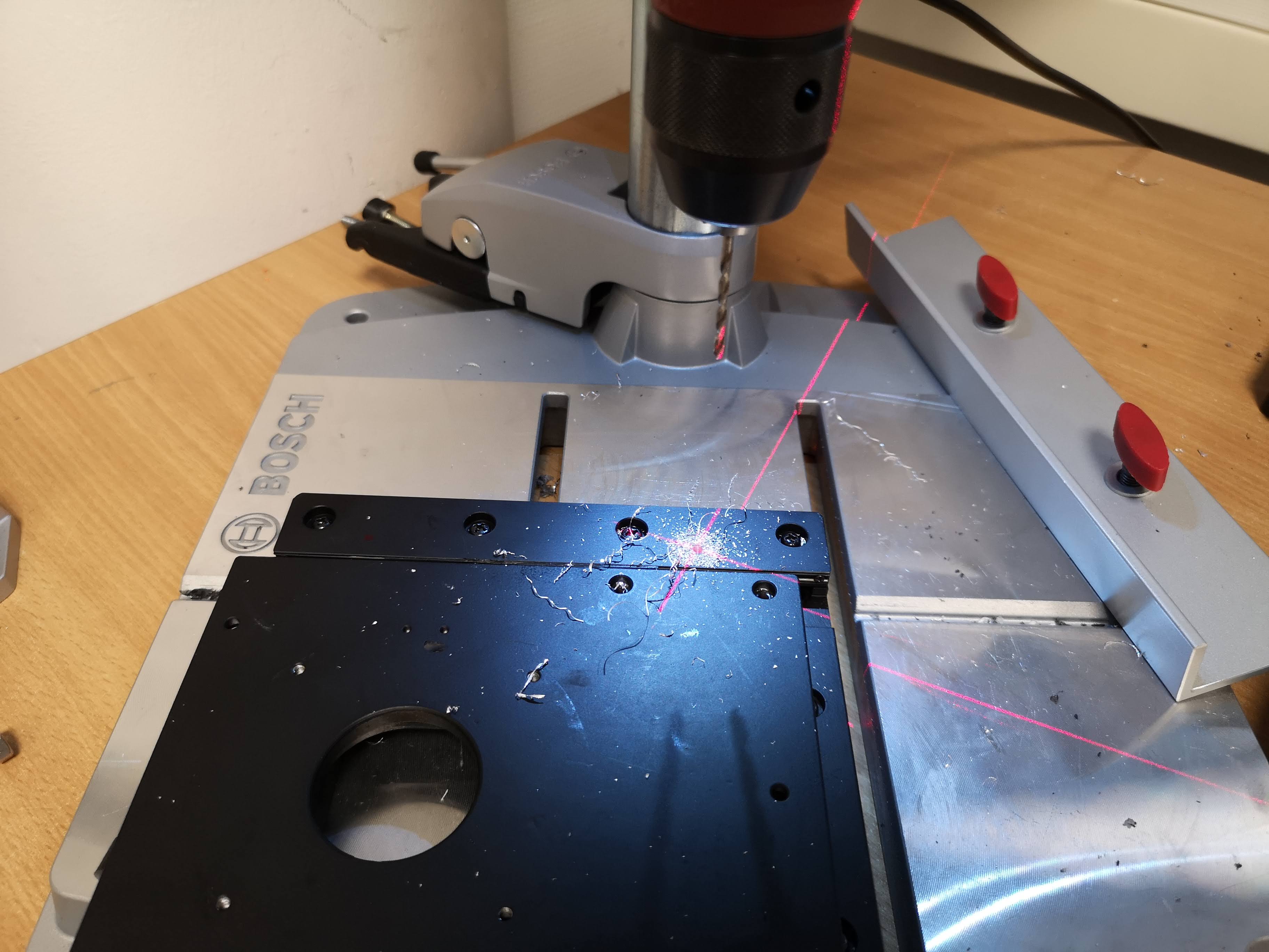
Take the Ständerbohrmaschine and use a drill for the M3 Tap. Make through holes everywhere, where you marked the spots. Use safety goggles:
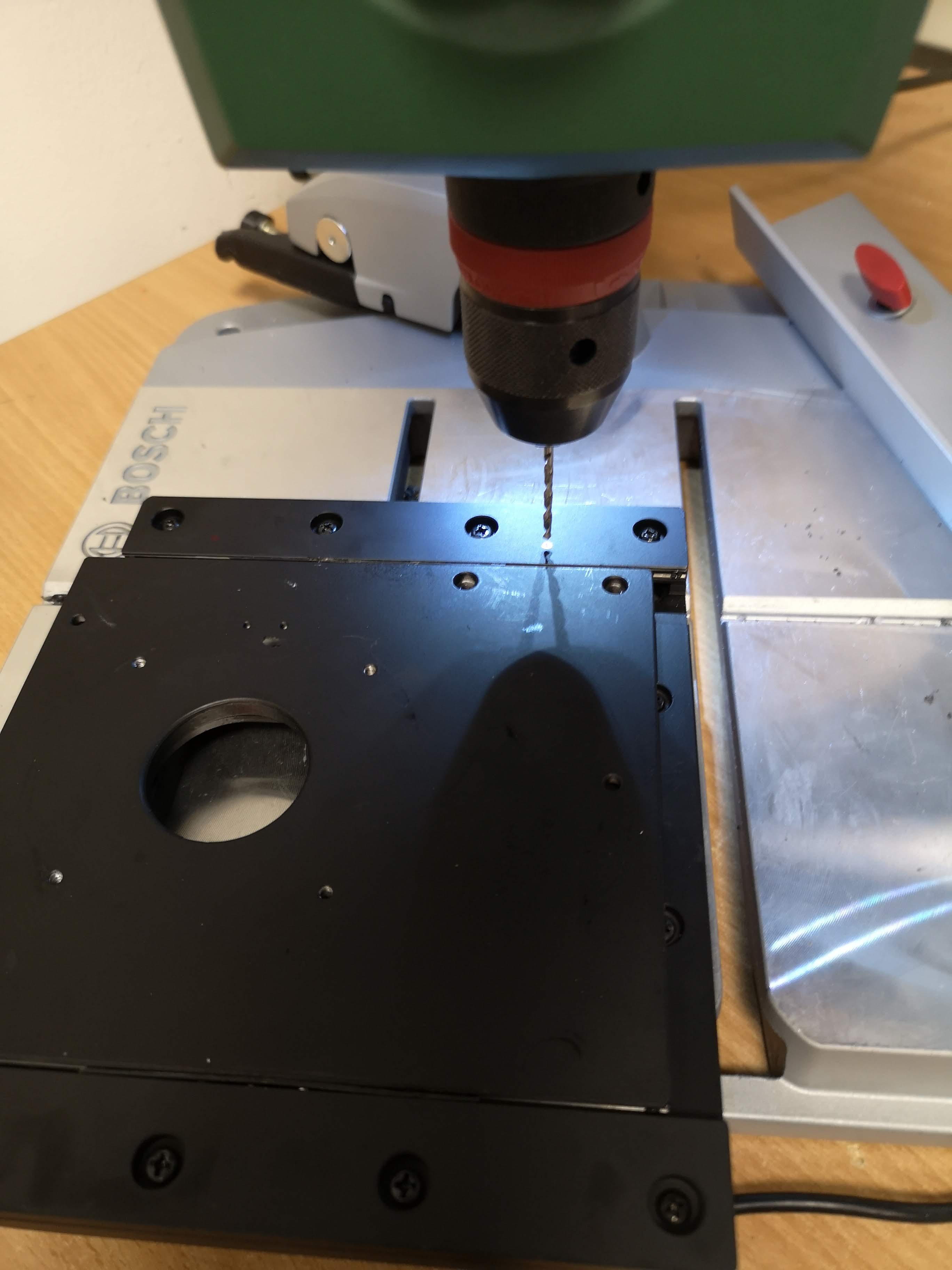
Remove dust with a vacuum cleaner
Cut taps. Make sure holes are clearn and through! Mount the linear motorized stage on the xy stage with M3 cylindrical screws (DIN908, 8mm)

Mount stage on the other side as well:

We also need to add the M5 long-rods (155mm). They have to fit through the holes of the uc2 mounting plate (see last step)

The metal-parts are done

Adding the auxilary/3D-printed parts
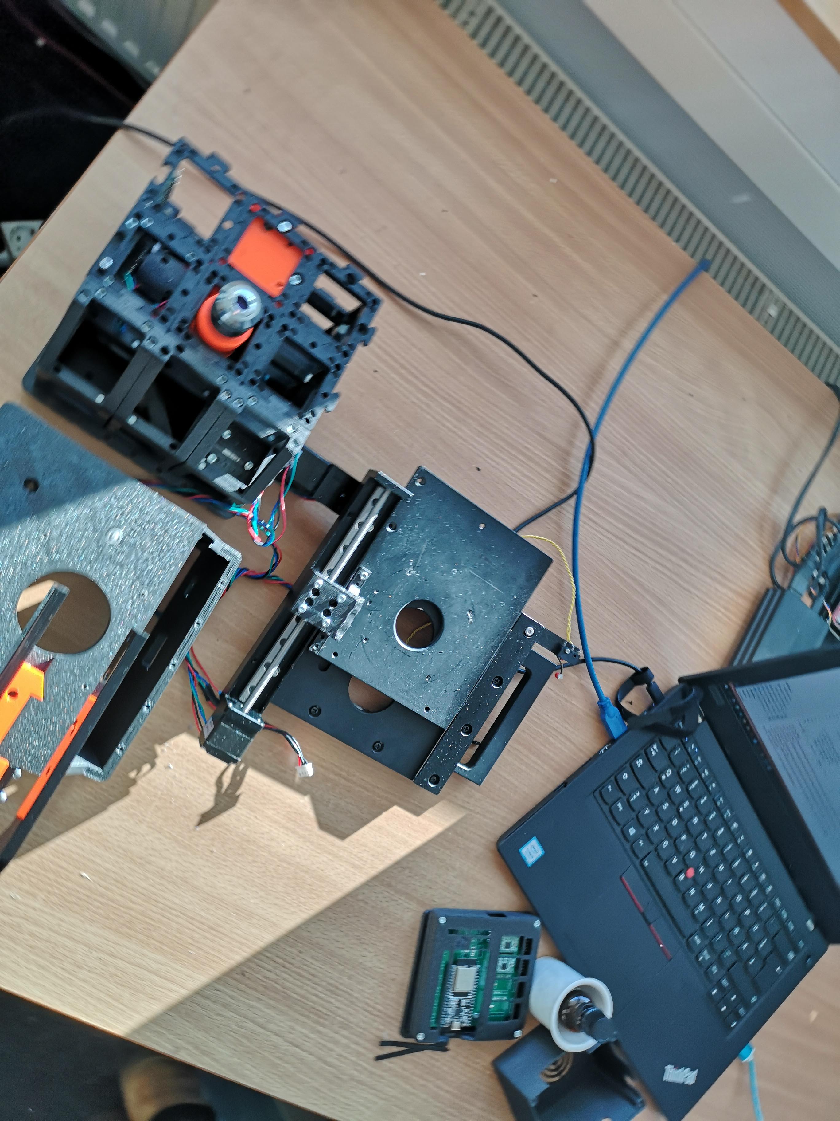
The remaining parts will first connect the linear motors to the stage in order to move it around and second, add a plate that mounts the stage to the cubes.
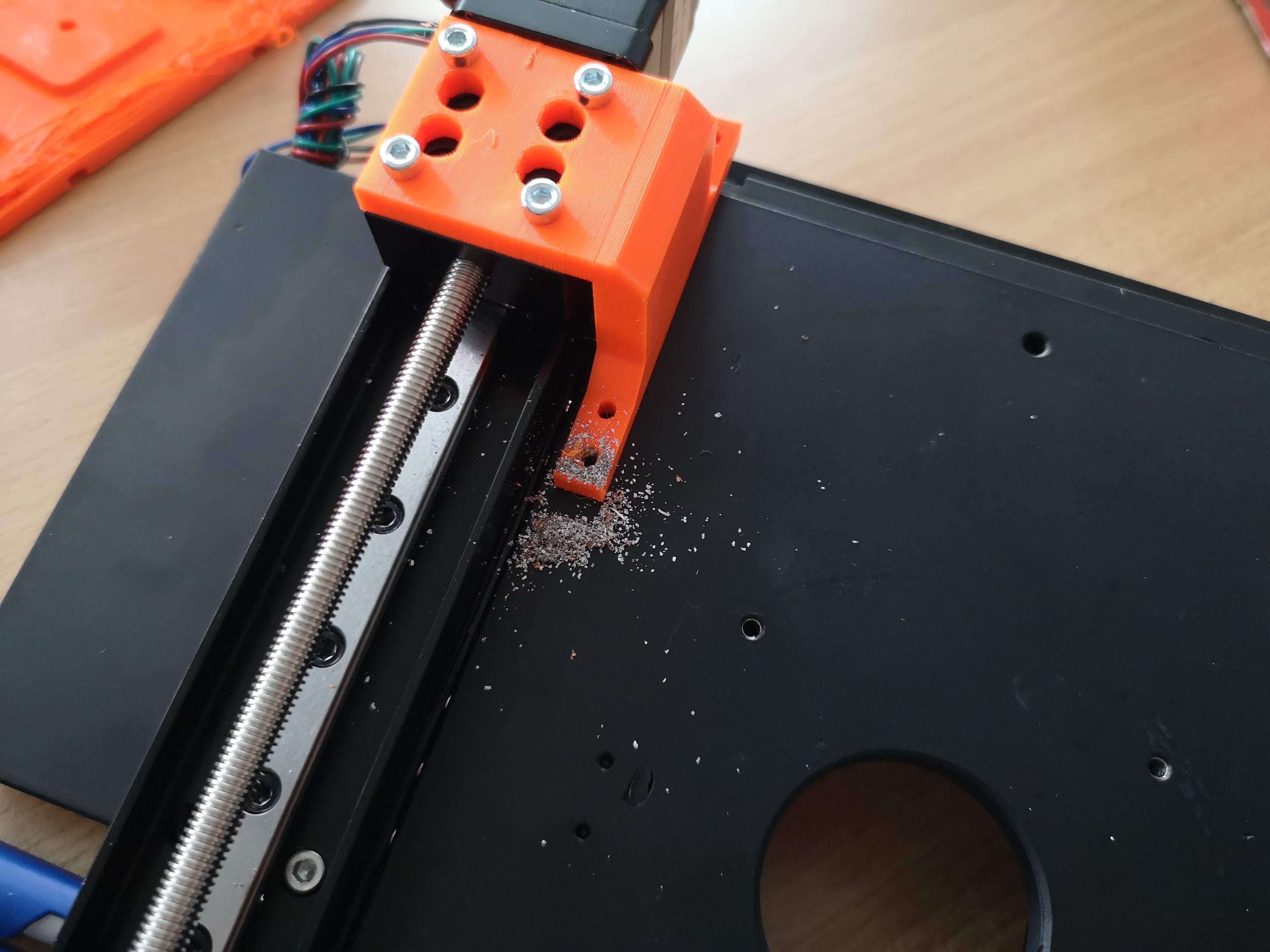
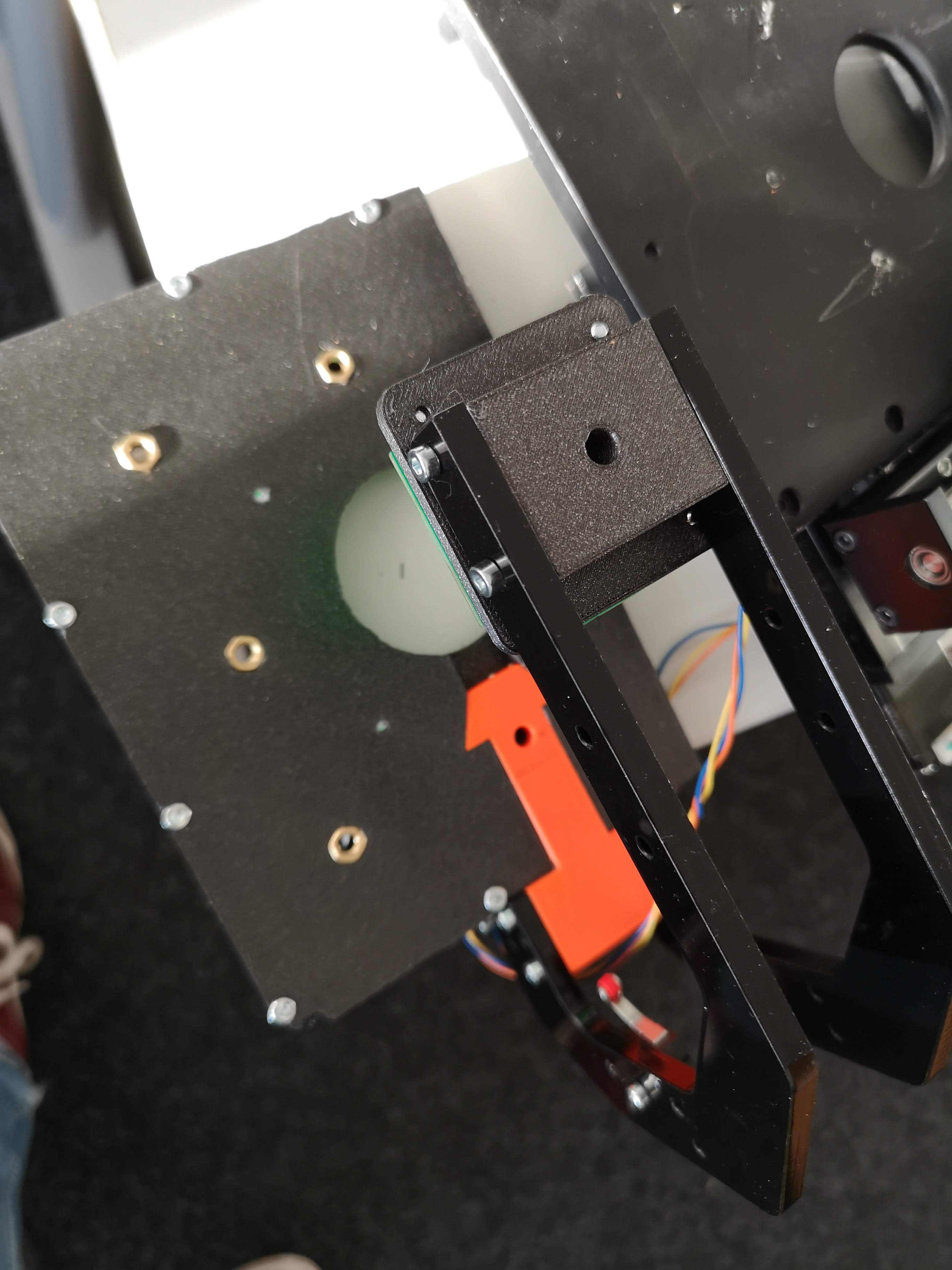
Add the mounting arm on the upper part:

Add the mounting arm on the lower part:
Equip the Plate with the Illumination adapter (which side depends on the later assembly - if not fluorescence, it doesn't matter) The M5 nuts are not necessary anymore. The remaining holes help you guiding the M5 rodsinto the holes. (see former photo) Add M3 screws to the plate from above such that you have open-ended threads lurking from the other side (hardly visible TODO: add image!)

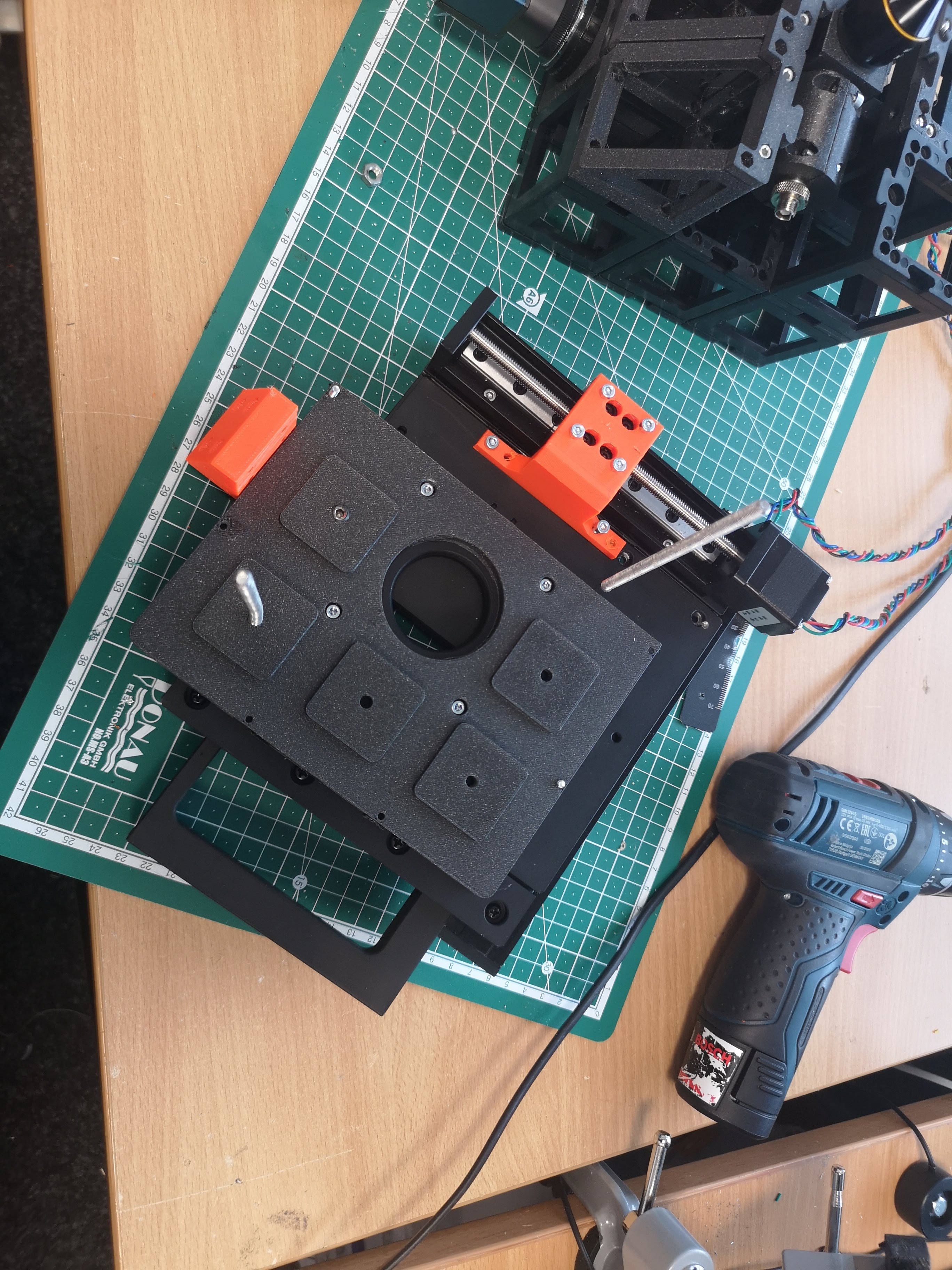
Fixate the illumination arm holder with the metal stage using an M3 hole (eventually drill a hole 2.7mm)
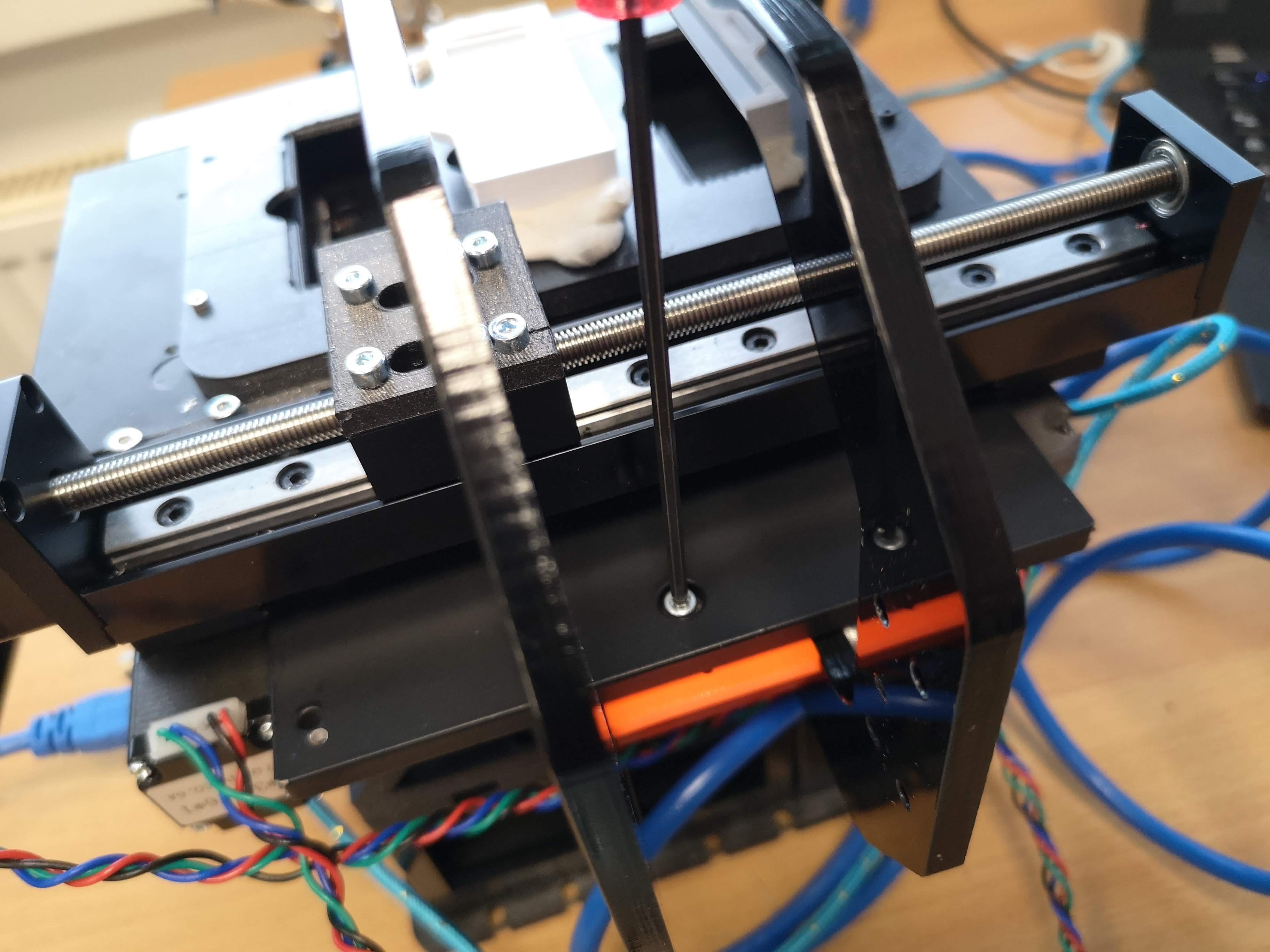
Screw the plate to the M3 screw holes on the xy stage (bottom part). The stage should look like this. Now, we can continue to the next step.
Prepare the Z-stage
The documentation for the motorized 25mm Z-stage can be found here: https://openuc2.github.io/docs/PRODUCTION/PG_12_STAGE_Z_NEMA
Once done, lock the Stage with the Puzzle piece with M5x8 worm screws:
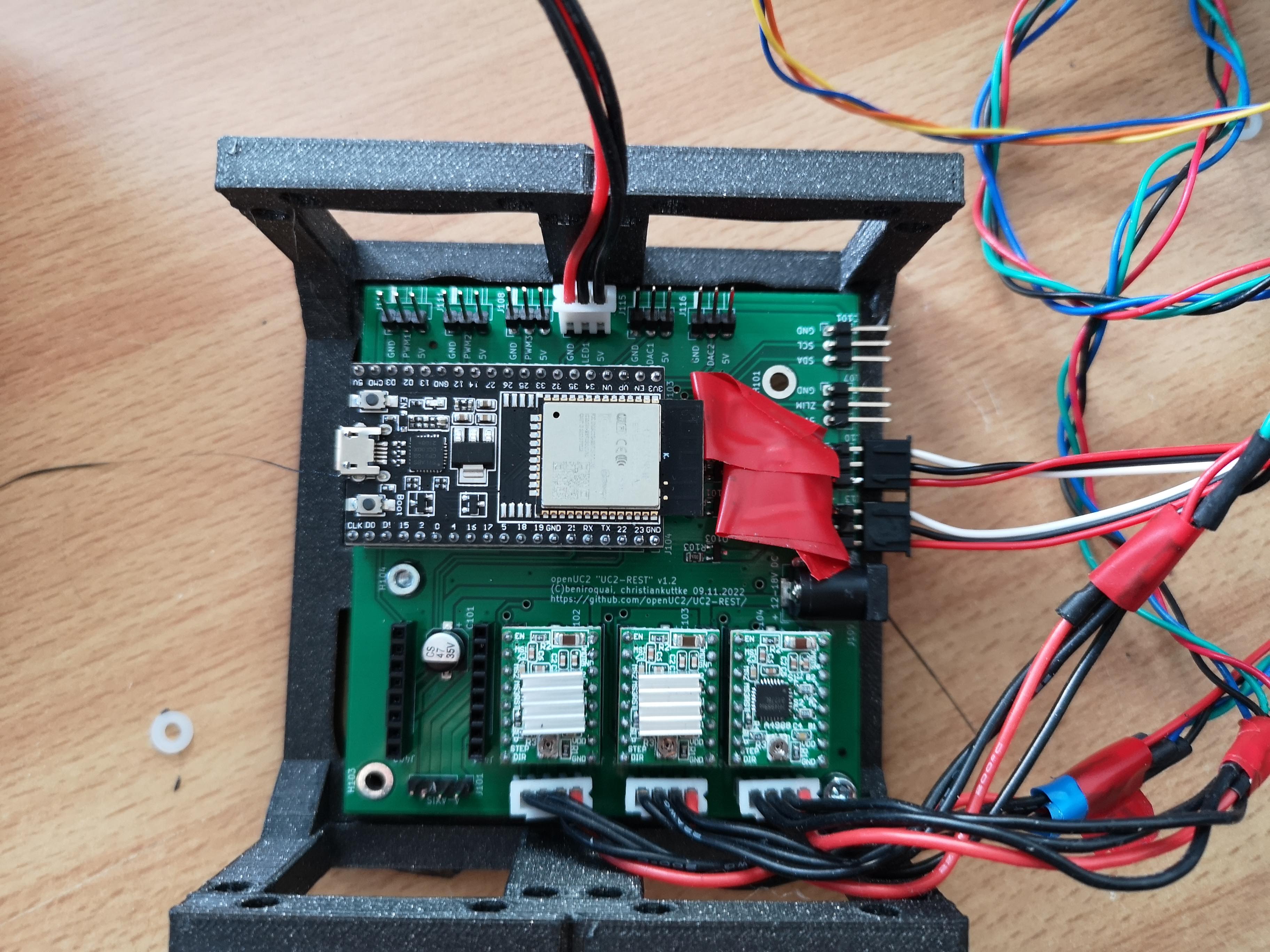
Prepare Electronics
Bill of Material
- UC2e v2 electronics
- 3x A4988 Stepper driver
- 12V power supply
- USB micro cable
- 3D printed case
- 2x puzzle pieces
- 8 M5x8 thread-only screws
- 4x M3x8mm screws
Assembly
Attach the electronics board to the 3D printed assembly and tighten it with the M3 screws (cylindrical, Din906) Attach the puzzle pieces to the distal ends of the assembly and lock it with the M5 screws. For this the yet closed holes have to be opened by "drilling" it through.
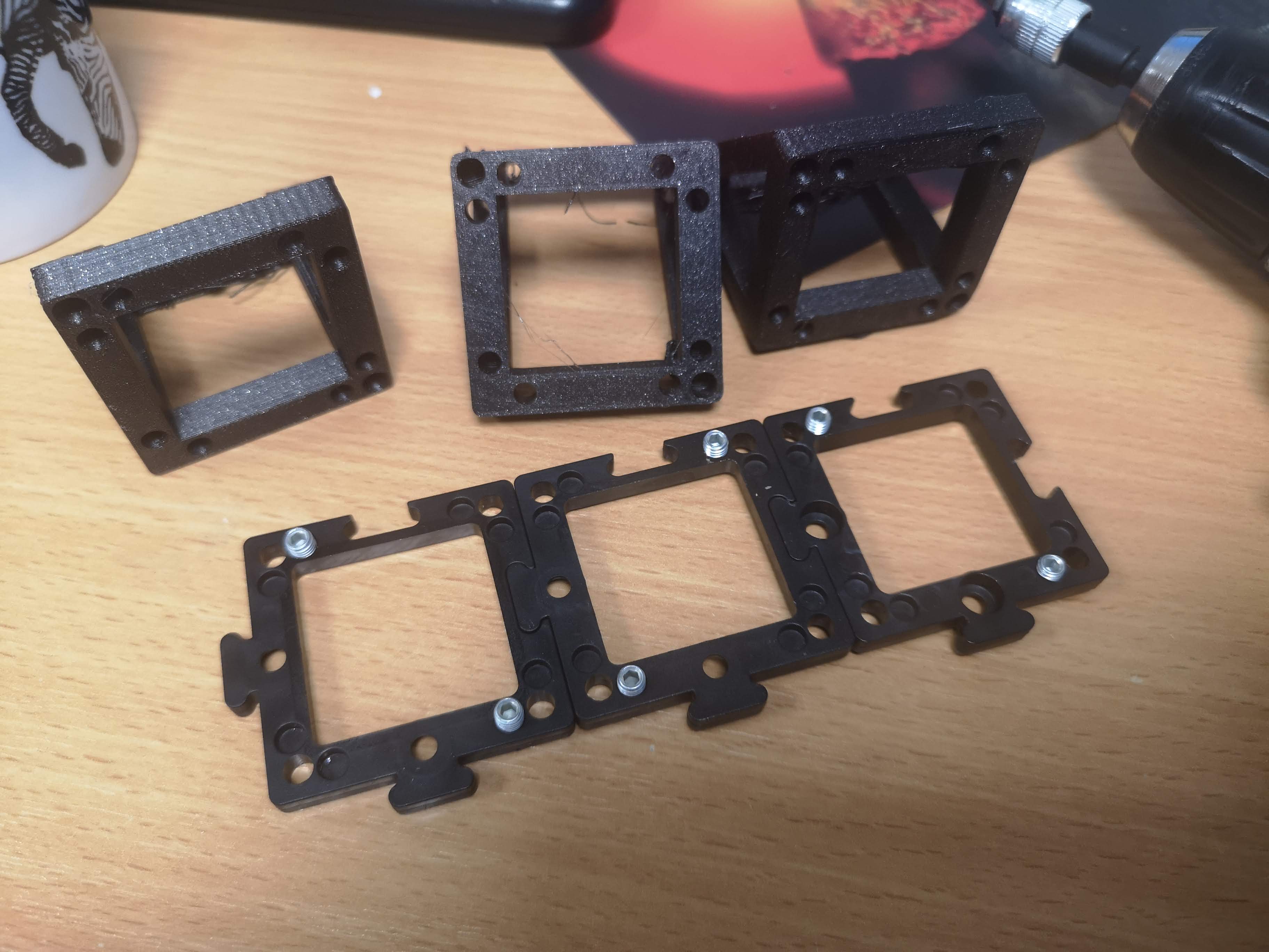
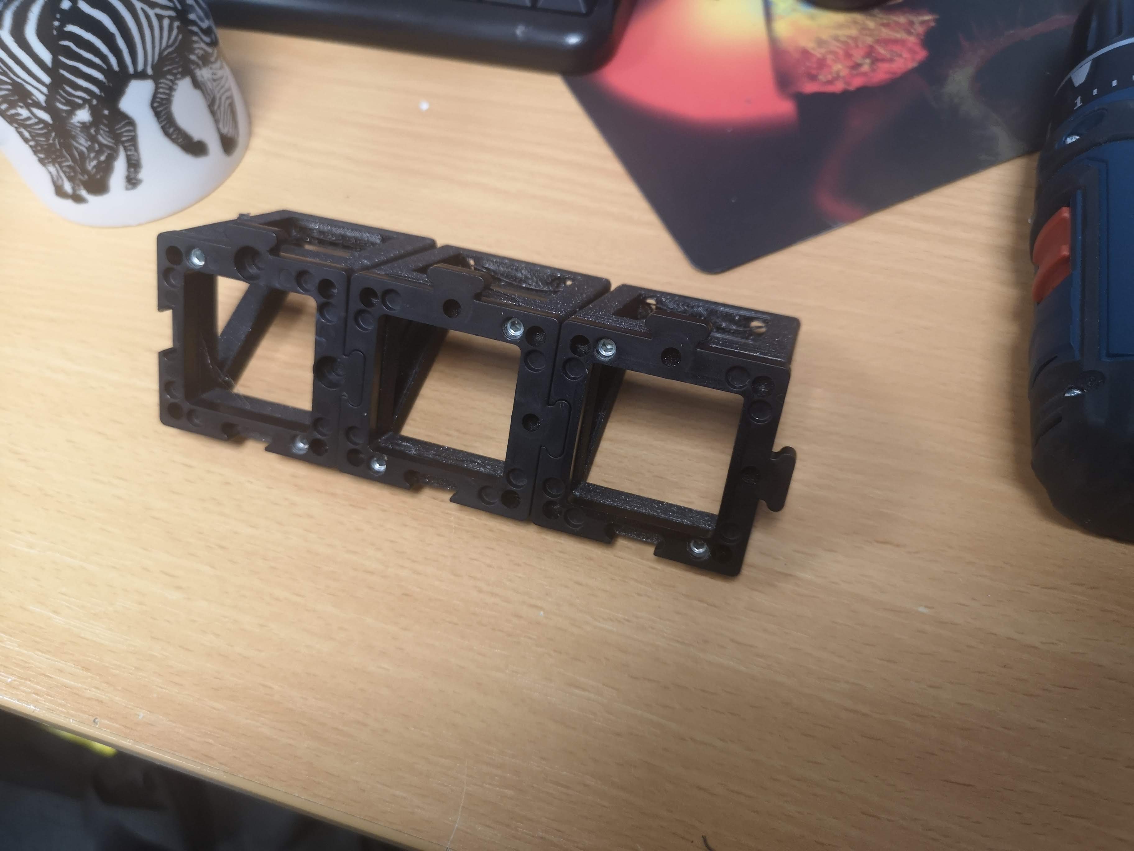
Prepare Triangle Structure
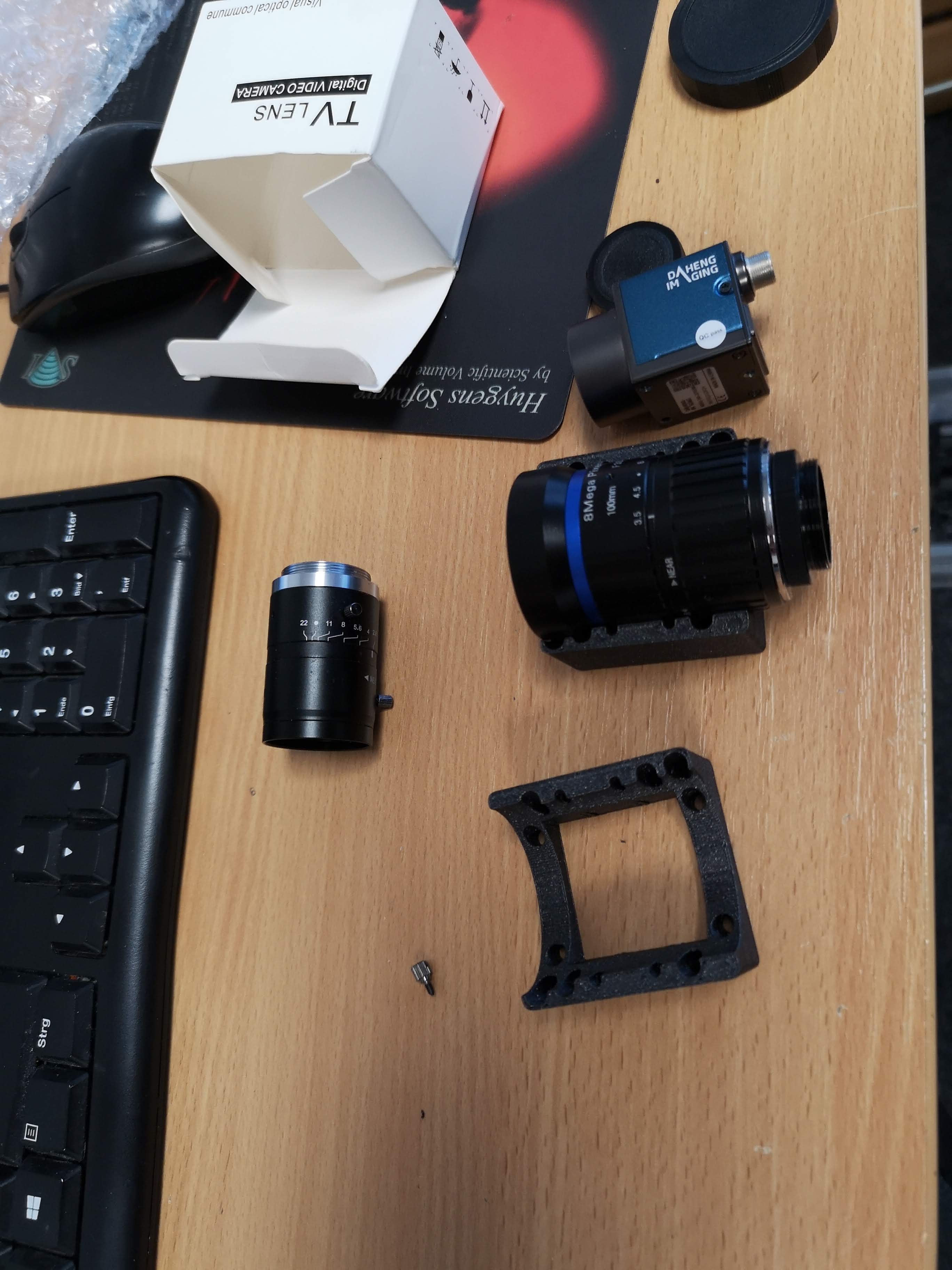
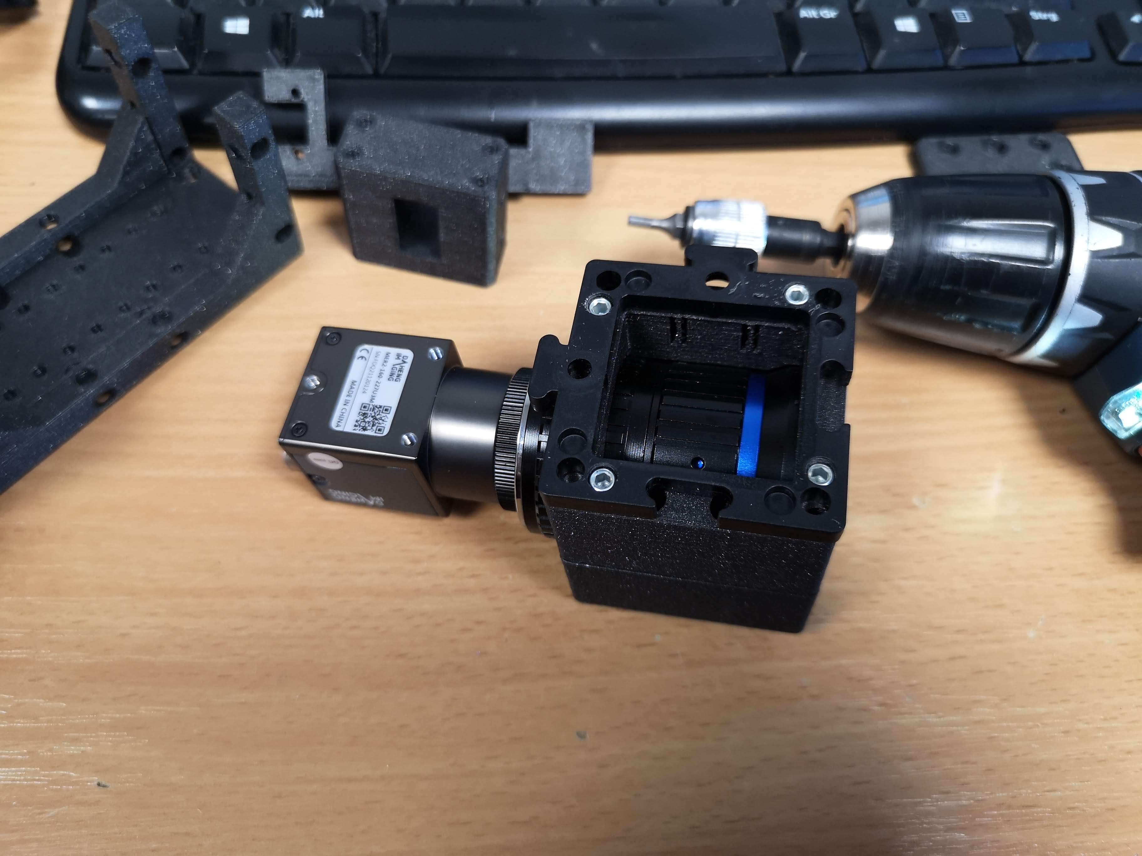
Tubelens
Bill of Material
- Berrybase 100mm CCTV Lens
- Daheng Vision IMX226 sensor
- USB 3 Camera Cable
- 2x Puzzlepieze
- 8x M5x8 mm worm screw
- 4x M3x18mm screw
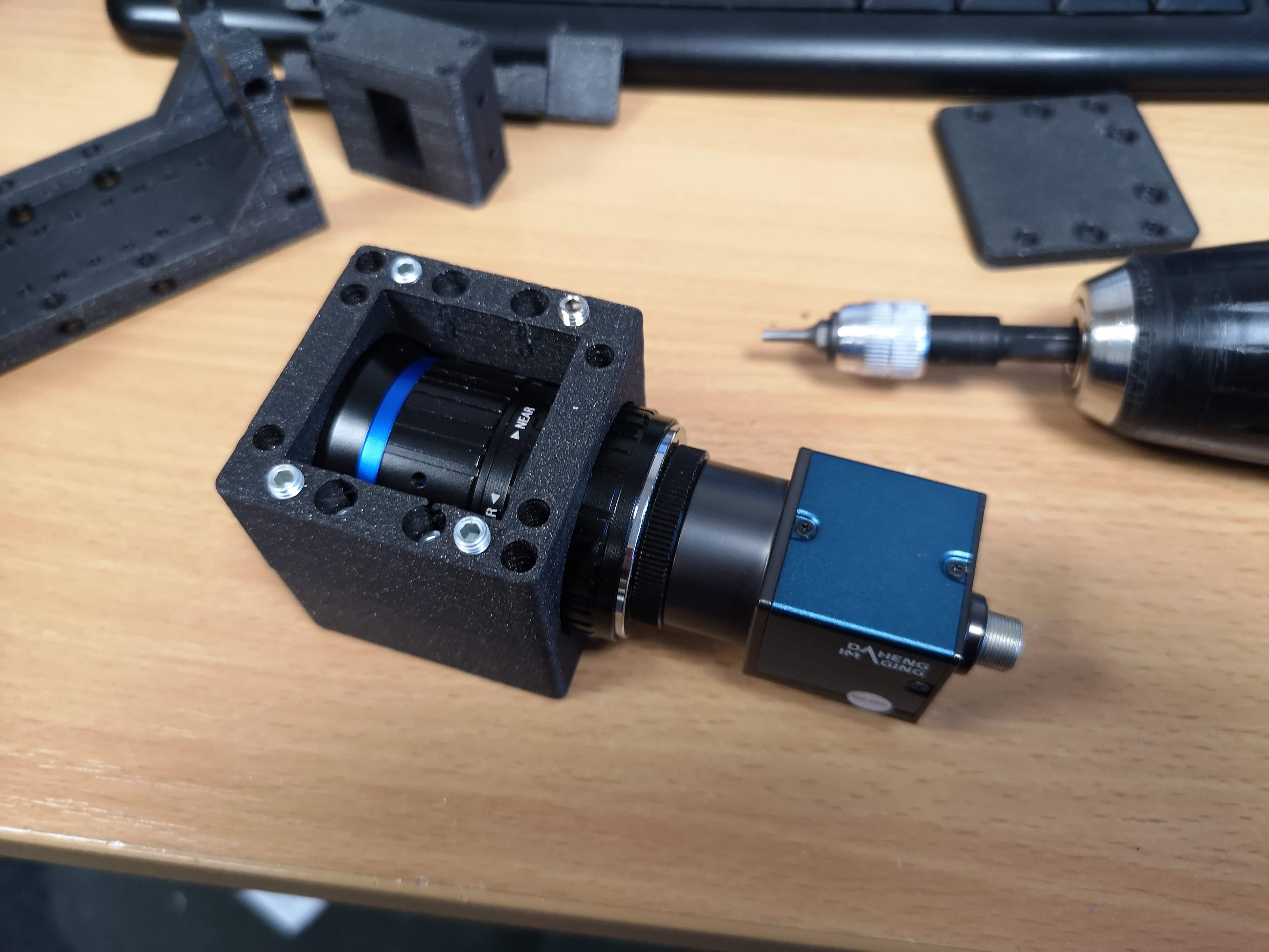
Assembly


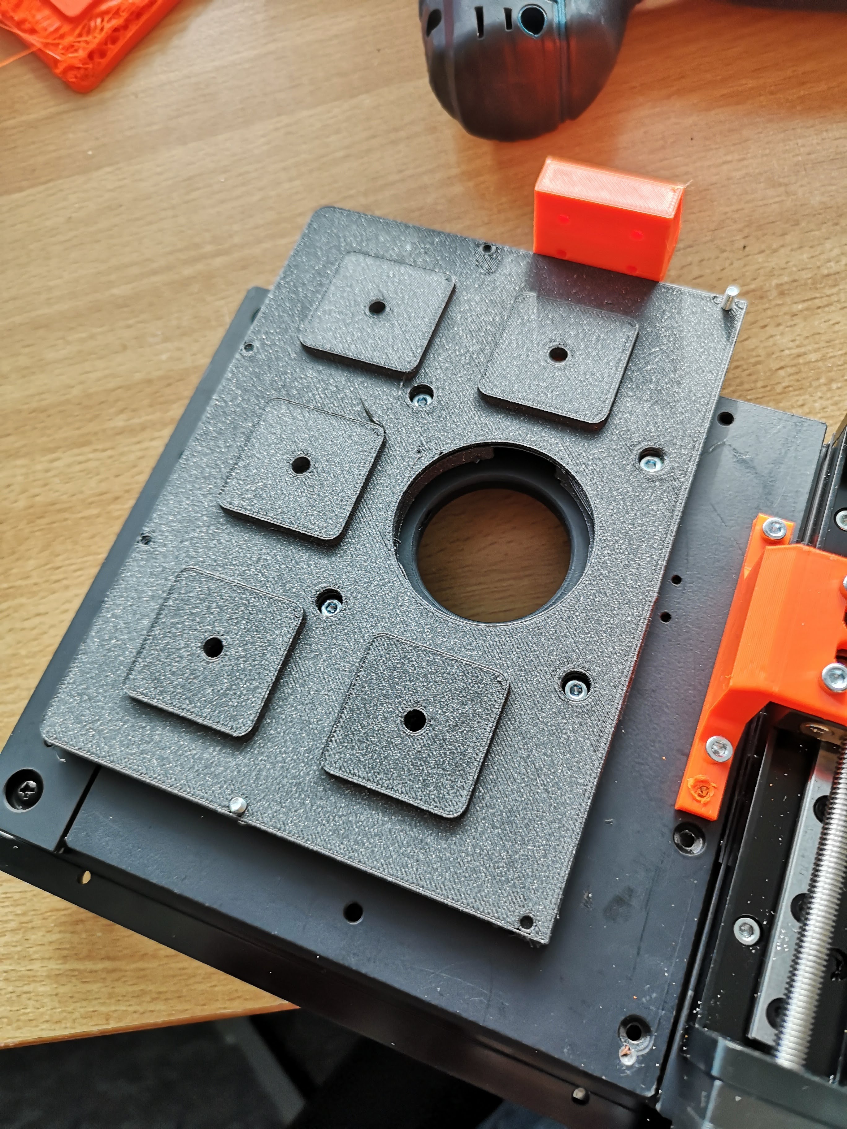
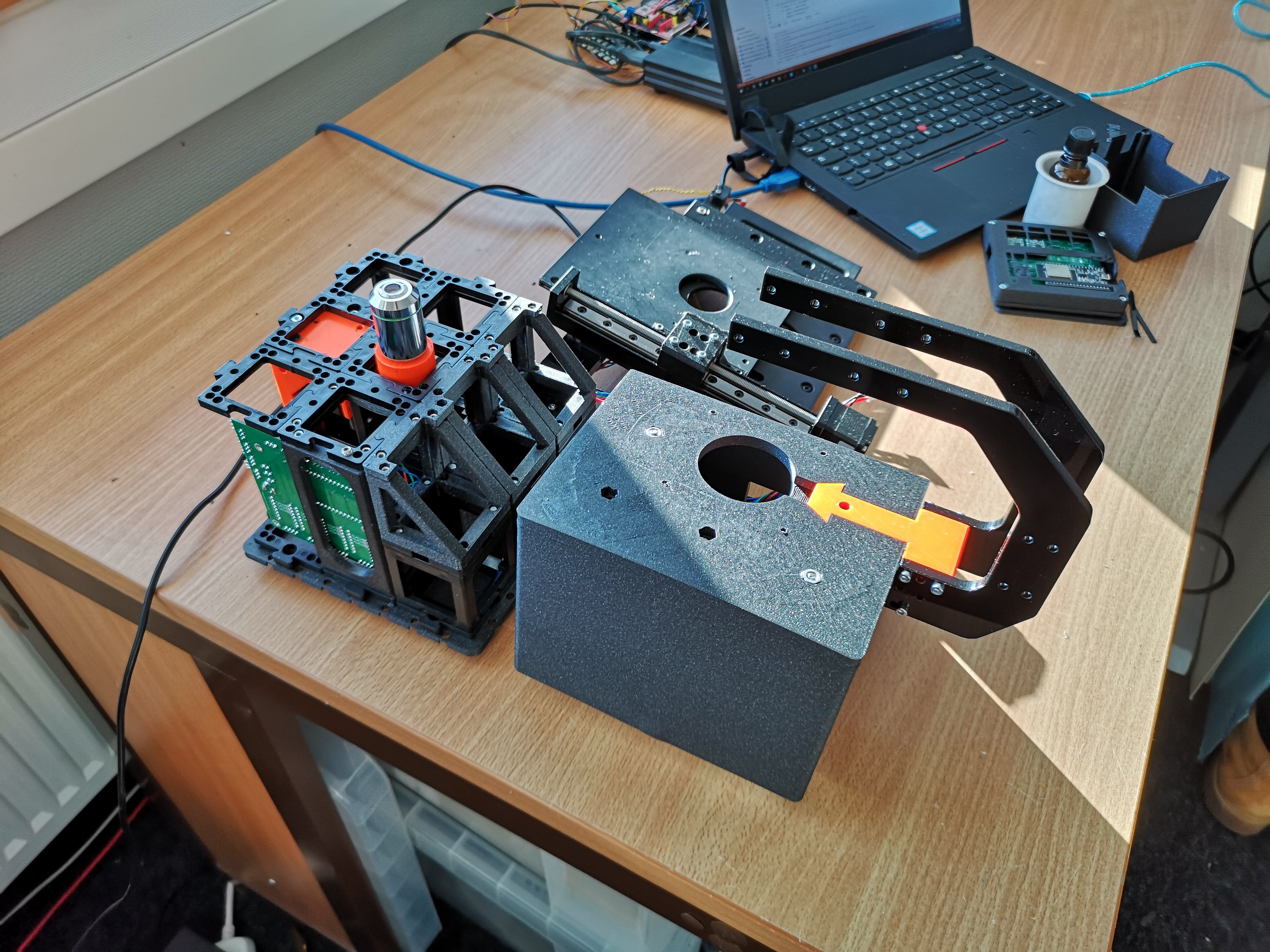
Adding the Baseplate


Endstops and Illumination

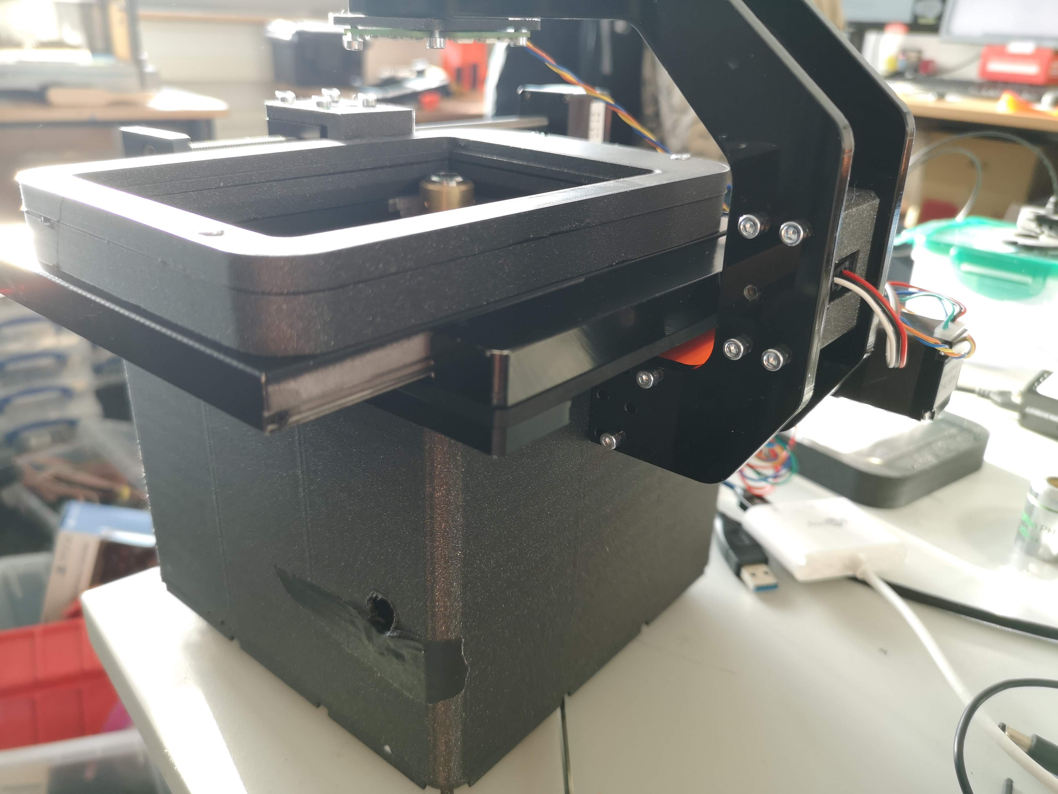
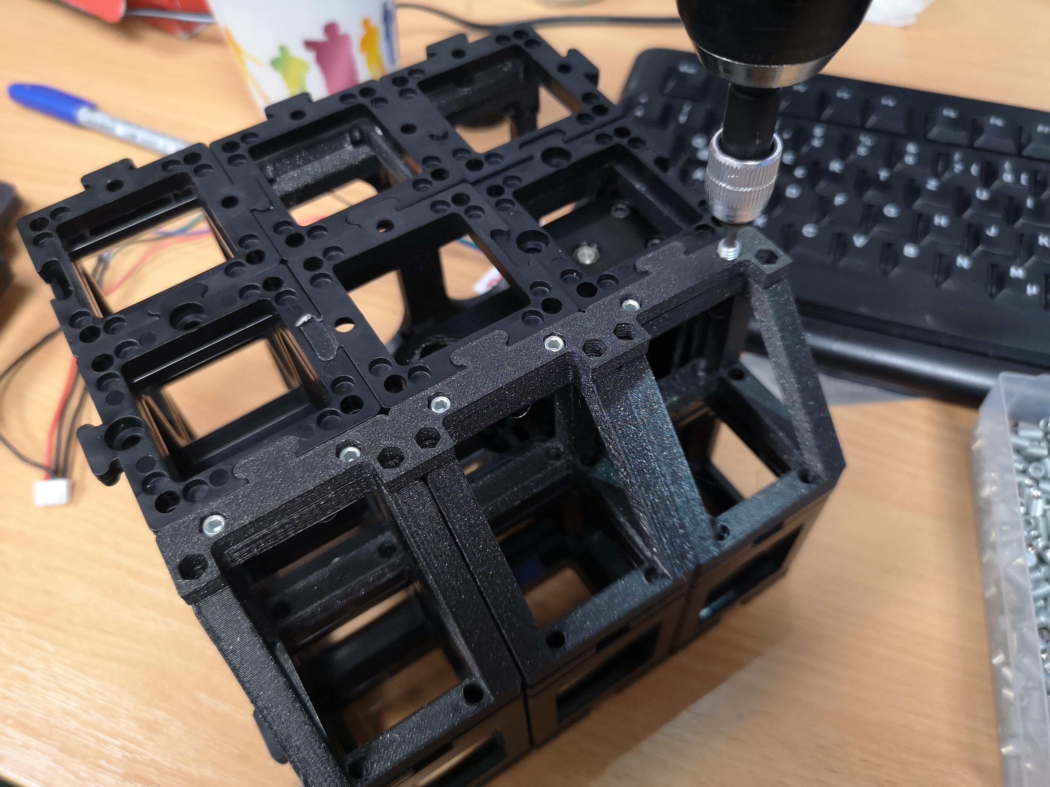
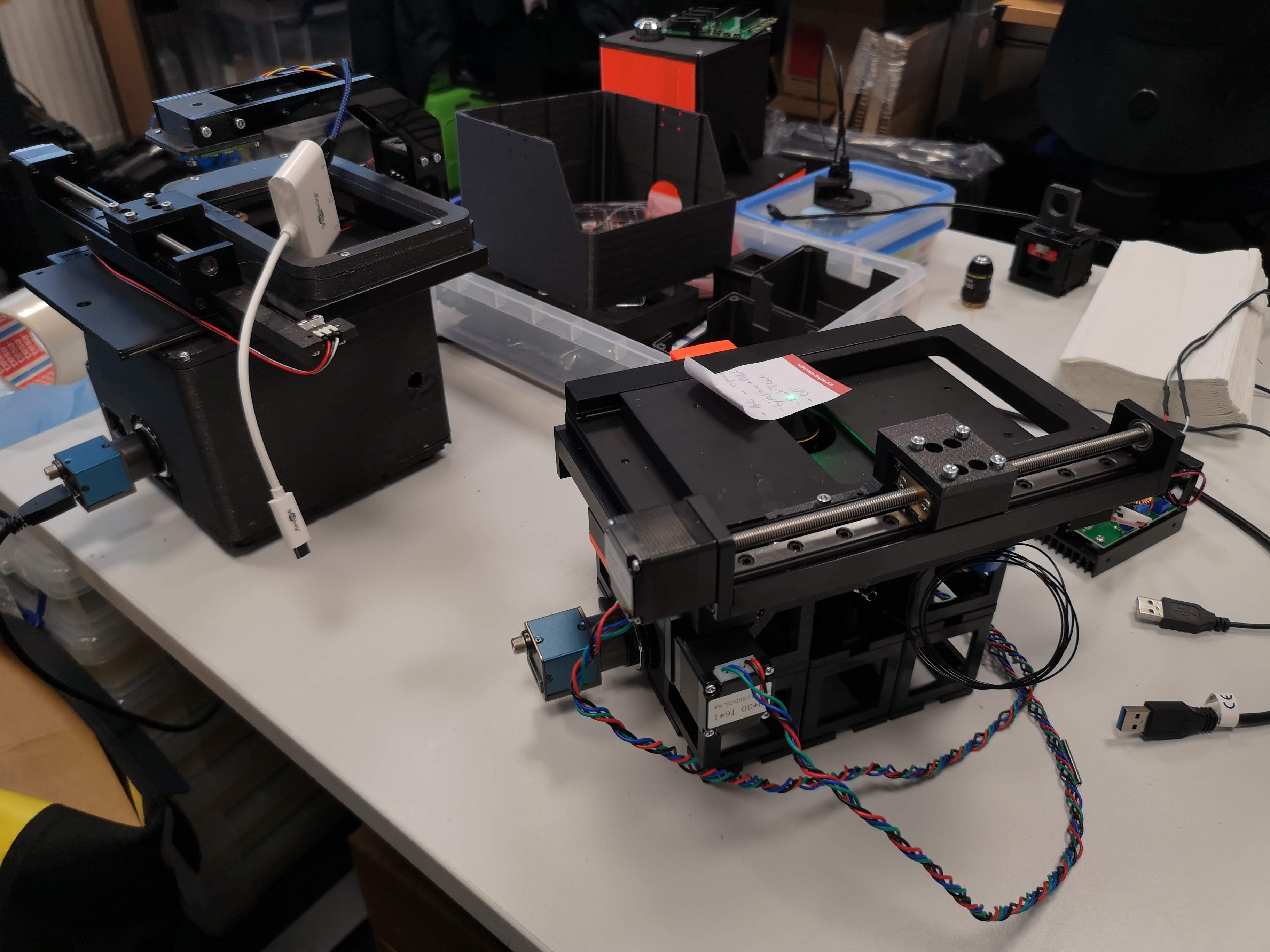
Skeleton
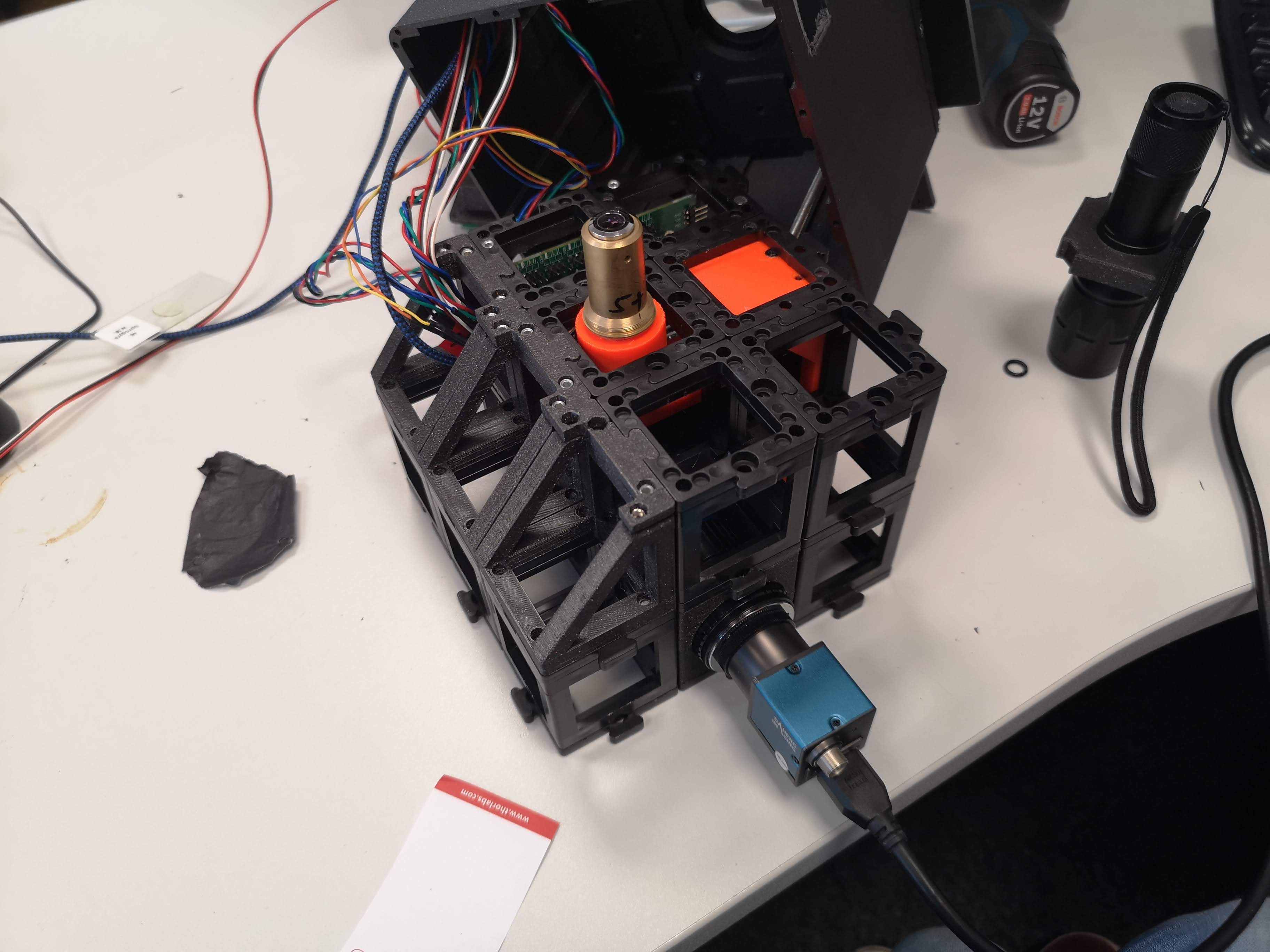


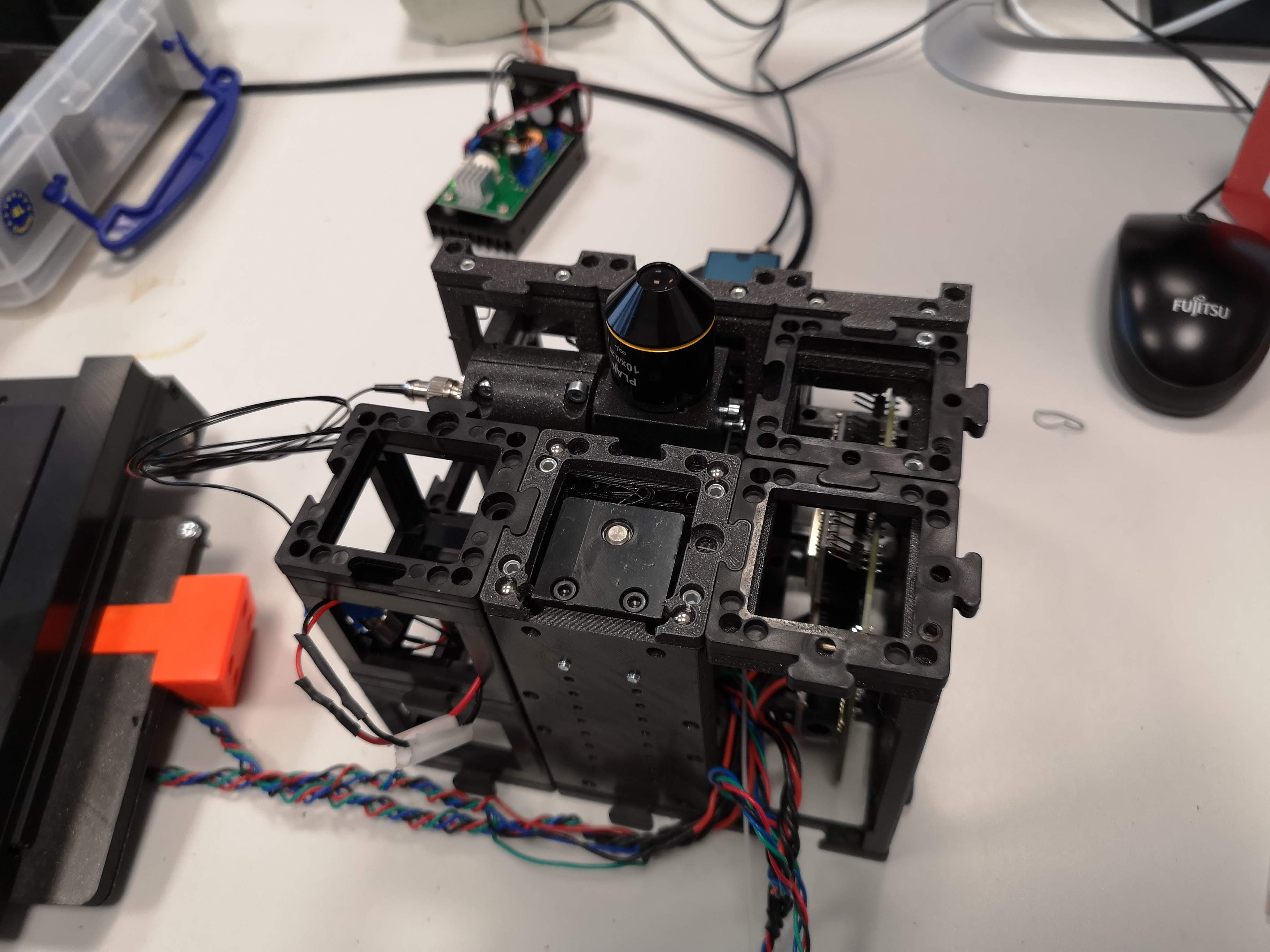
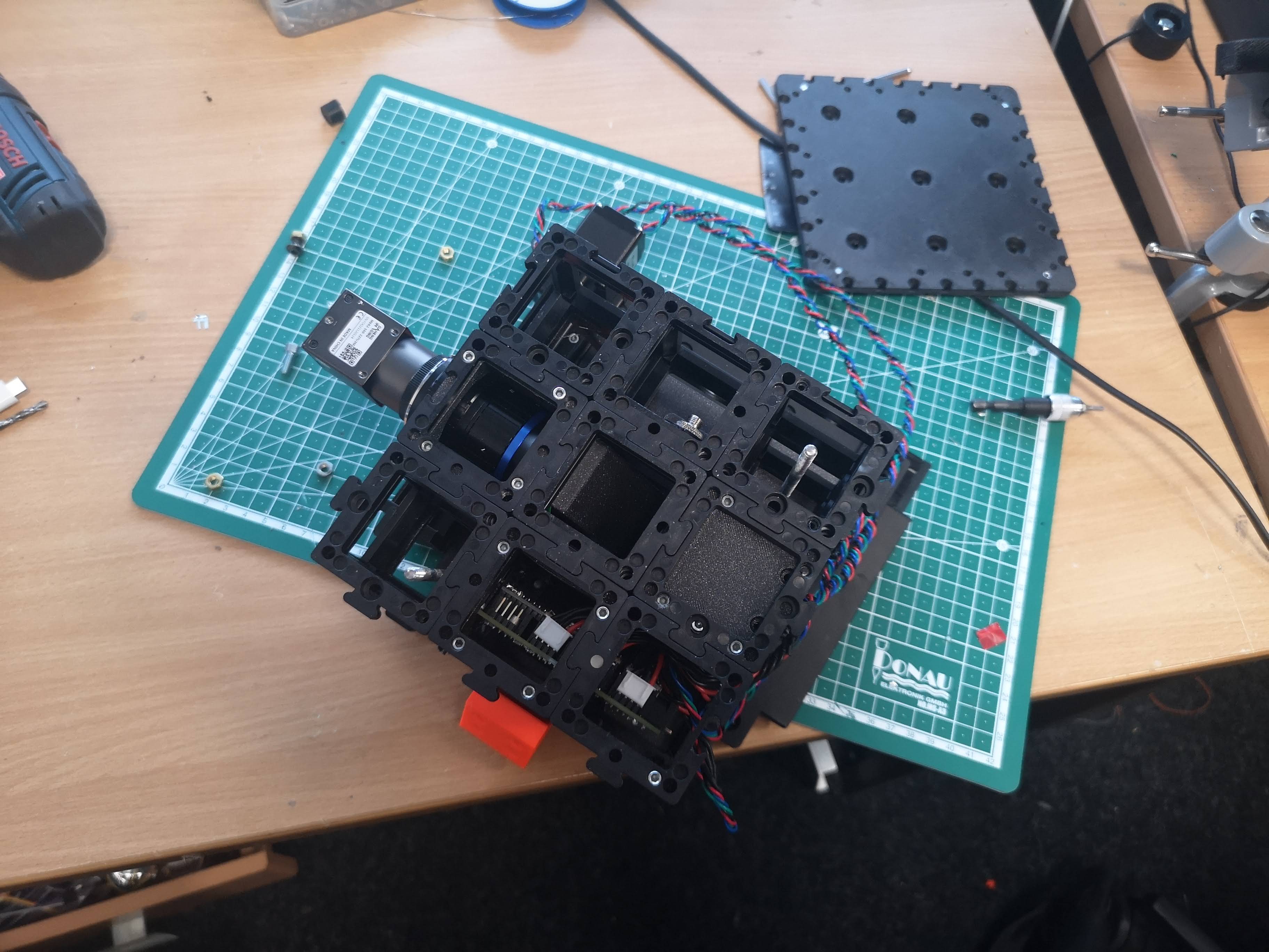
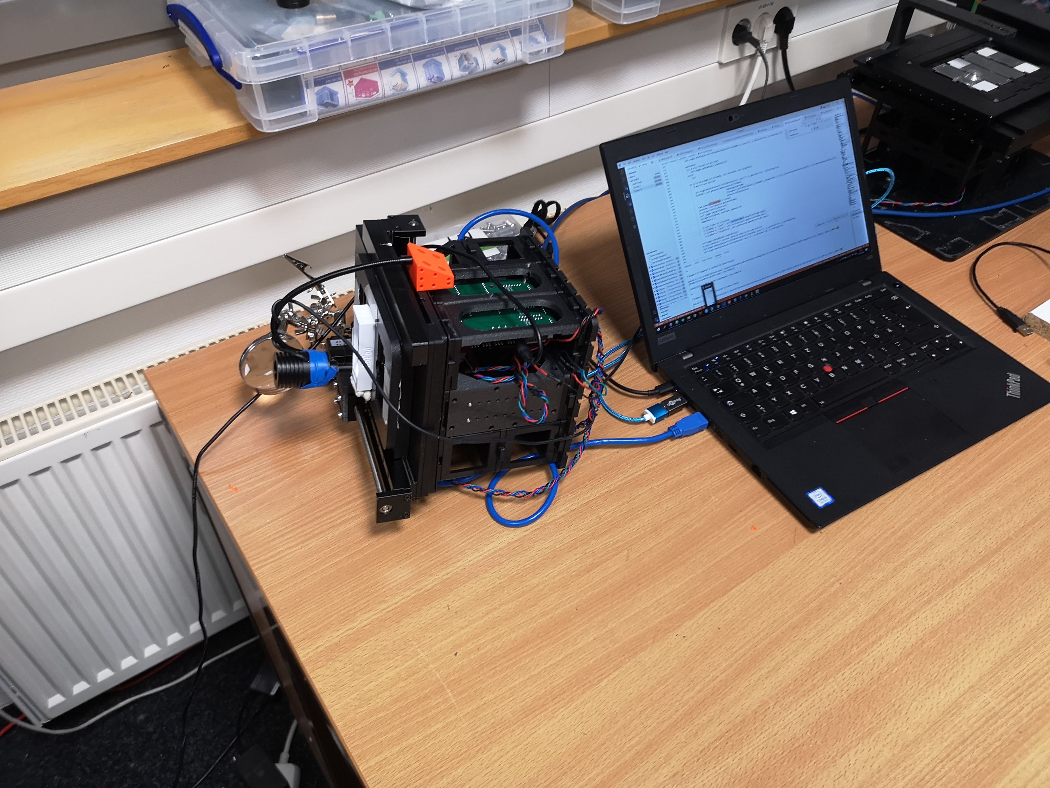
Fully Assembled

Fluo Extension

Improvements
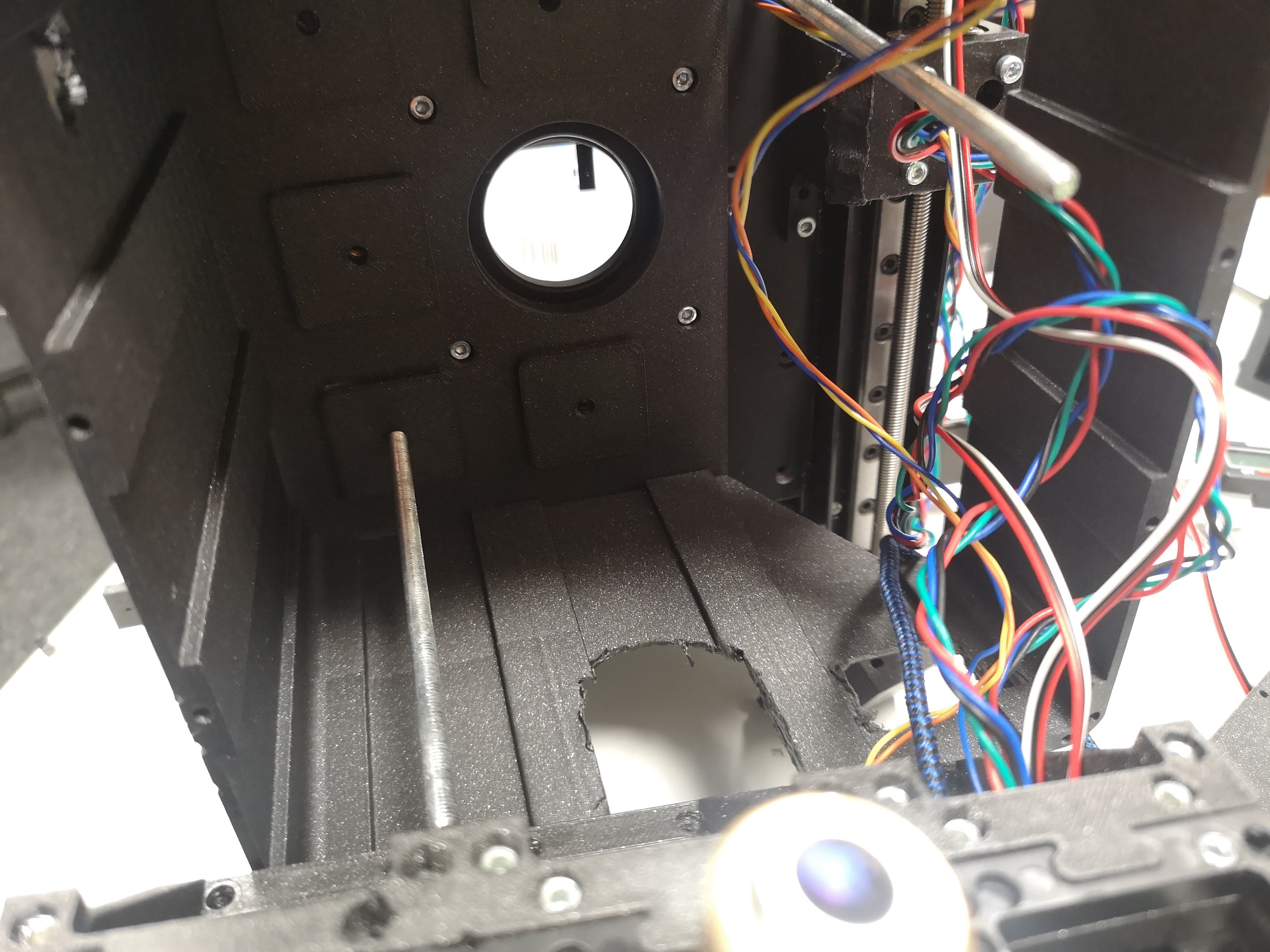
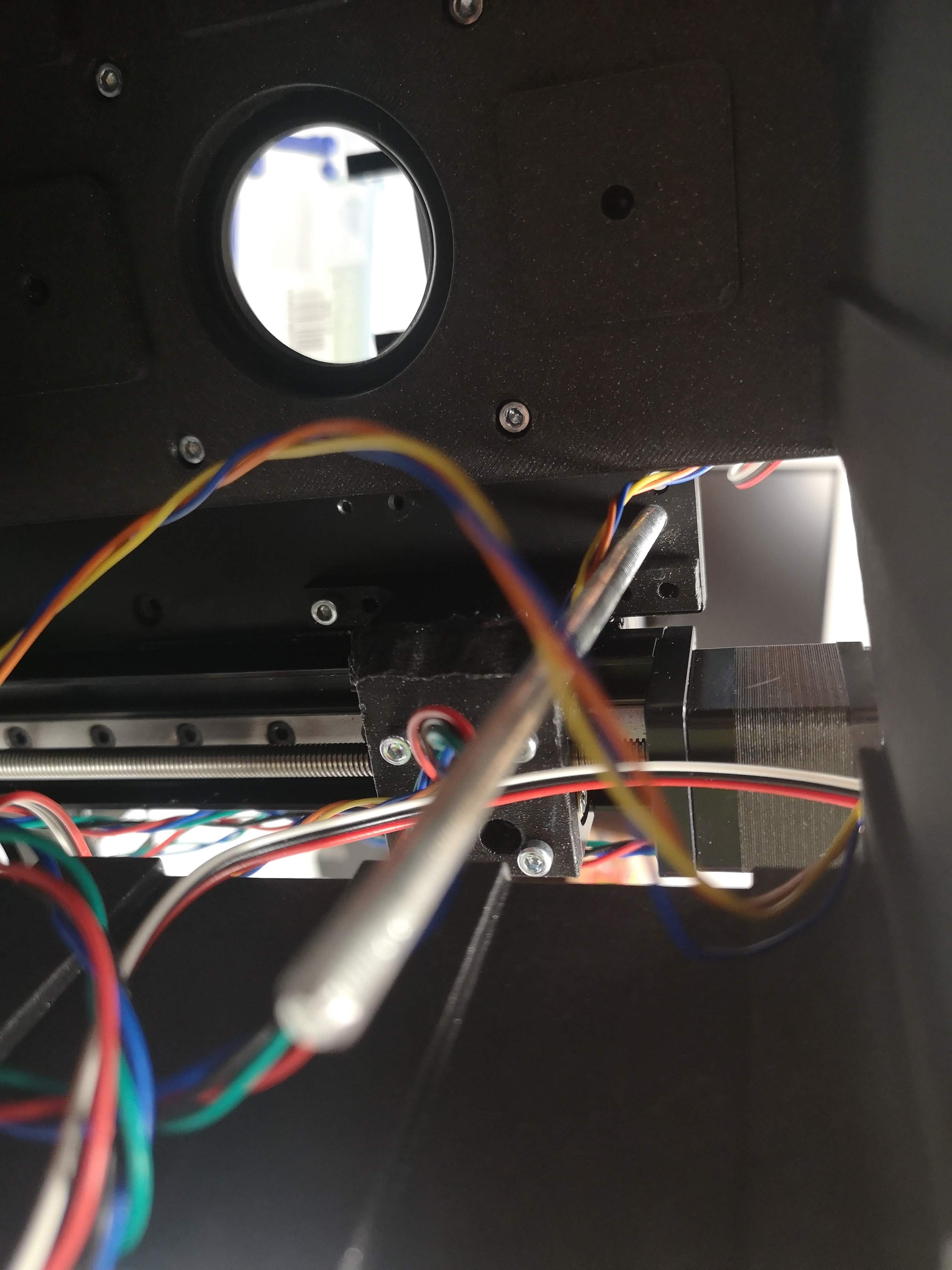
Stage does not run smoothly
You can release the pressure on the linear bearings by loosening the screws carefully. Make sure you don't introduce unneccesary play. The stage works with two v-grooves and balls in between.


Additional images (have to be sorted)


Safety
TODO: Add additional information!
- in case of shattered glass, make sure you don't cut yourself
- Make sure you don't hurt yourself
- The moving parts can potentially hurt your finger
- The electronics - if used in a wrong way - can harm you
- edges may be sharp, make sure you don't cut yourself