Tutorial: Building a UC2 DMD-SIM for Optical Sectioning
In this workshop, we will guide you through building a low-cost, DMD-based structured illumination microscope (SIM) for optical sectioning. This system can be easily integrated into your existing wide-field fluorescence microscope, enabling you to achieve optical sectioning—essentially removing out-of-focus blur and improving image contrast.
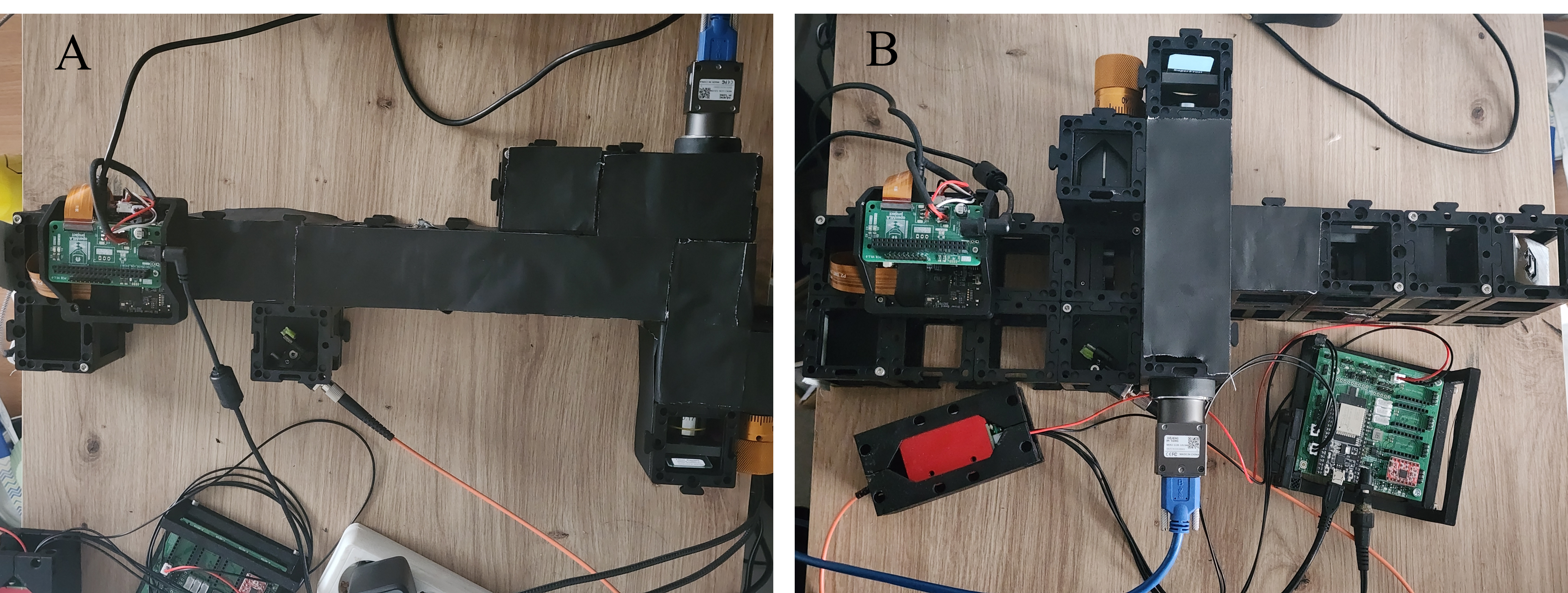 Figure 1: The two configurations built in this project. (A) Direct Projection setup where the DMD is imaged directly onto the sample. (B) 4f Interference setup using a Fourier filter to remove higher diffraction orders.
Safety Warning ⚠️
Laser Safety: This setup involves a 488 nm laser. Always wear appropriate safety goggles.
DMD Diffraction: When installing and debugging the DMD, be extremely careful with the diffracted laser light. The DMD acts as a grating, and the reflected light will split into multiple diffraction orders. Ensure that stray beams are properly blocked and do not enter your eyes or scatter dangerously in the room.
Theory of Operation
Structured illumination microscopy (SIM) works by illuminating the sample with a known spatial pattern (in our case, stripes), instead of uniform light. By acquiring images with different pattern phases and combining them mathematically, you can extract information about in-focus light and suppress out-of-focus background.
In a typical OS-SIM experiment, the illumination pattern is described as a sinusoidal function. We acquire three images with phase shifts , , and .
Using the RMS reconstruction algorithm, the optically-sectioned image is extracted:
Materials Needed
Optical Components
- Laser: 488 nm diode laser (fiber-coupled)
- Objective: 10× Plan Objective (NA = 0.25)
- Tube Lens: f = 100 mm
- Projection Lens (Direct Setup): f = 200 mm (Thorlabs AC254-200-A-ML)
- Relay Lenses (4f Setup): 2x f = 50 mm (Thorlabs AC254-050-A-ML)
- Filters:
- Dichroic Mirror (45°)
- Emission Filter (matched to sample)
- Spatial Filter (pinhole/slit for 4f setup)
Electronics & Computing
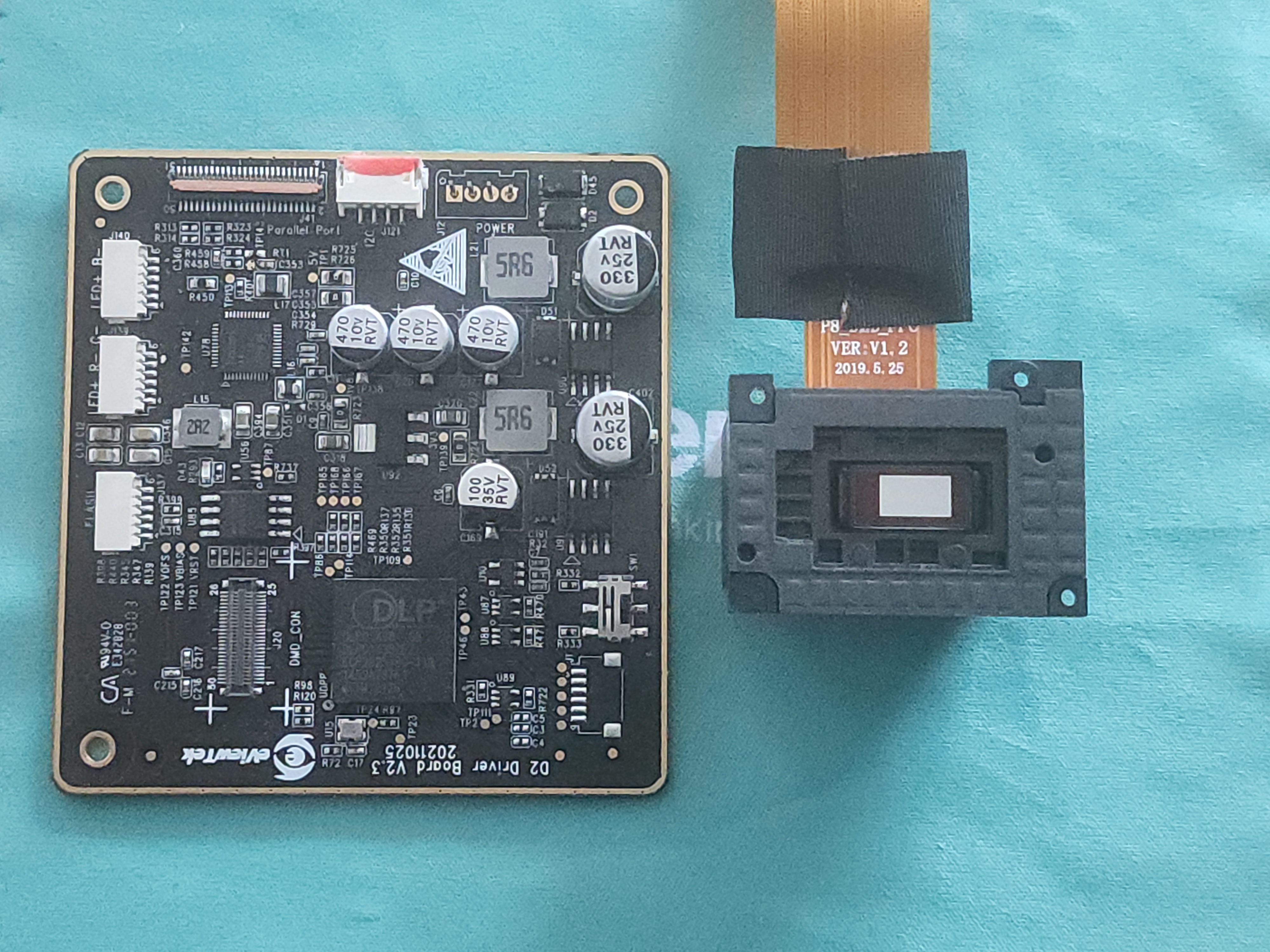
- DMD: DLP300S chip + DLPC1438 controller (harvested from Anycubic Photon Ultra 3D printer)
- Controller: Raspberry Pi Zero 2
- Interface: Custom Bridge Board (based on OpenMLA)
- Power: 12V Power Supply
Mechanical Components
- OpenUC2 System: Standard cubes and mounting plates
- Custom Parts:
- 3D-printed base plates for DMD alignment
- Filter holders for blocking diffraction orders
Optical Setup
We designed and tested two configurations for the illumination path.
1. Direct Projection Configuration (Setup A)
This is the simplest approach. The DMD pattern is imaged directly onto the sample plane using a 4f imaging system formed by the projection lens and the objective.
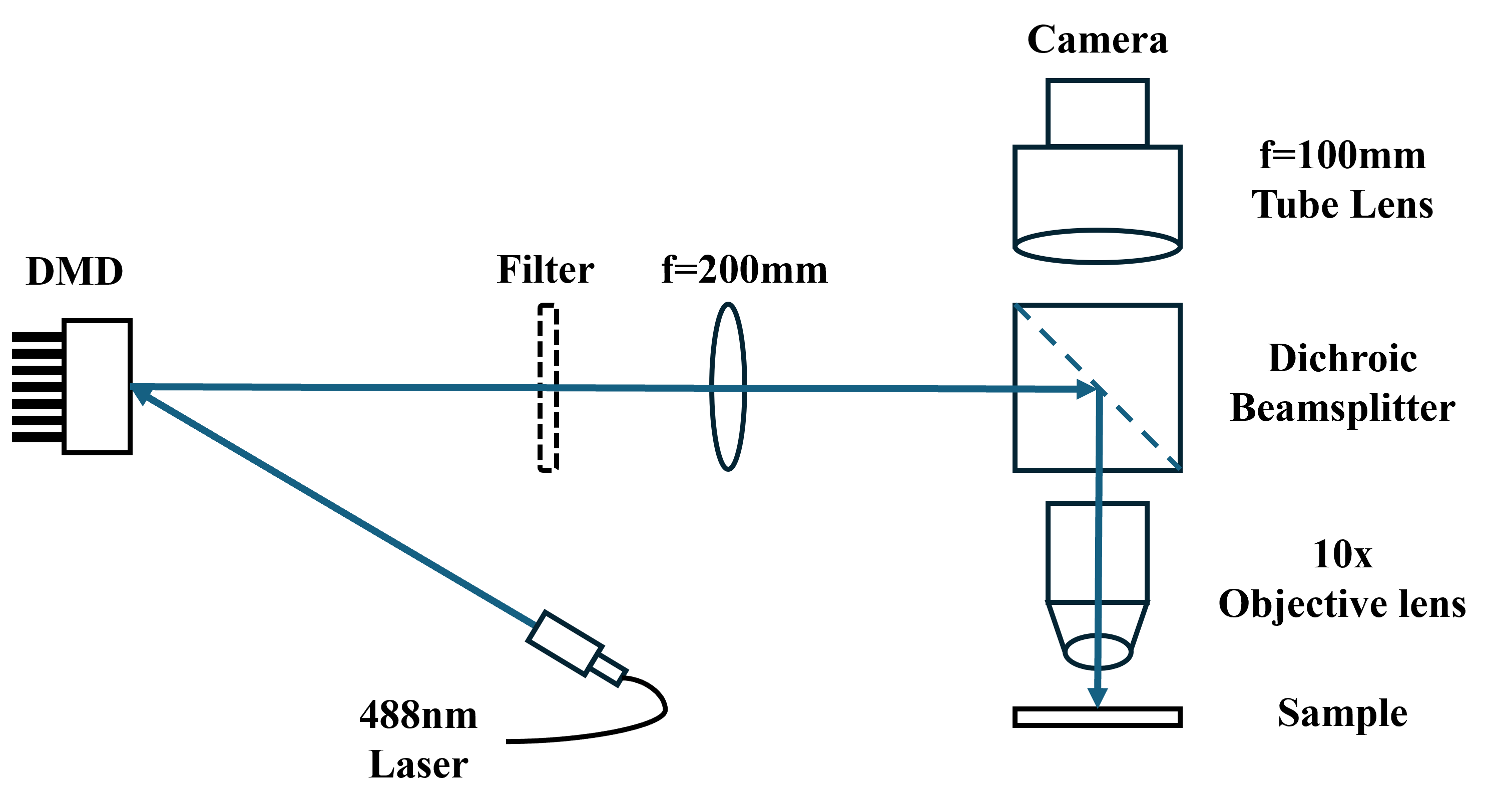
- Optics: 200 mm lens + 10× Objective.
- Magnification: (Pattern is demagnified 10×).
- Pros: Compact, fewer components, easier to align.
- Cons: Requires careful selection of pattern period to avoid artifacts from higher harmonics.
2. Fourier Filter Configuration (Setup B)
This configuration adds a 4f relay system with a spatial filter before the projection lens.
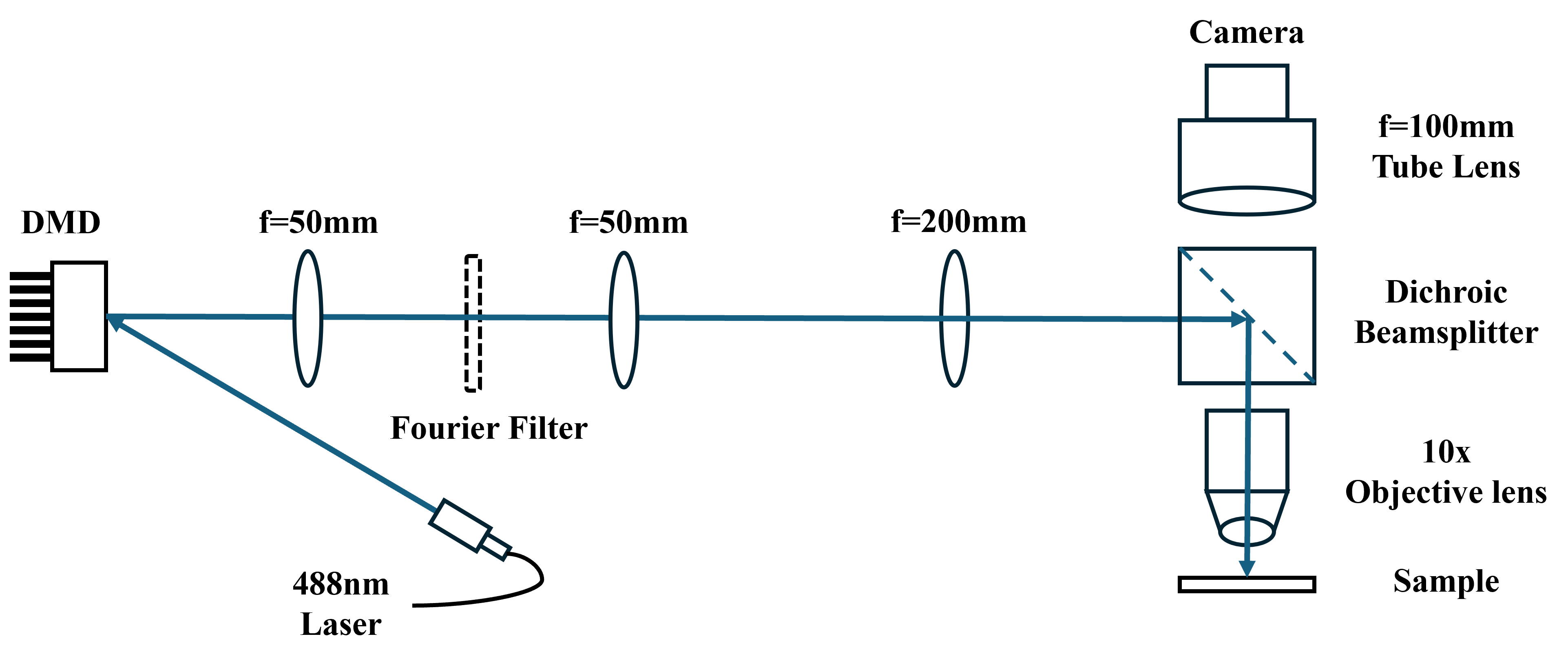
- Optics: Two 50 mm lenses forming a 4f system + Spatial Filter.
- Function: The spatial filter blocks unwanted higher diffraction orders (harmonics) from the binary DMD grating.
- Pros: Allows more flexibility in choosing the pattern period; produces a cleaner sinusoidal pattern.
- Cons: Larger footprint, harder to align, lower light efficiency due to filtering.
Experimental Setup
The system is built using the OpenUC2 modular standard.
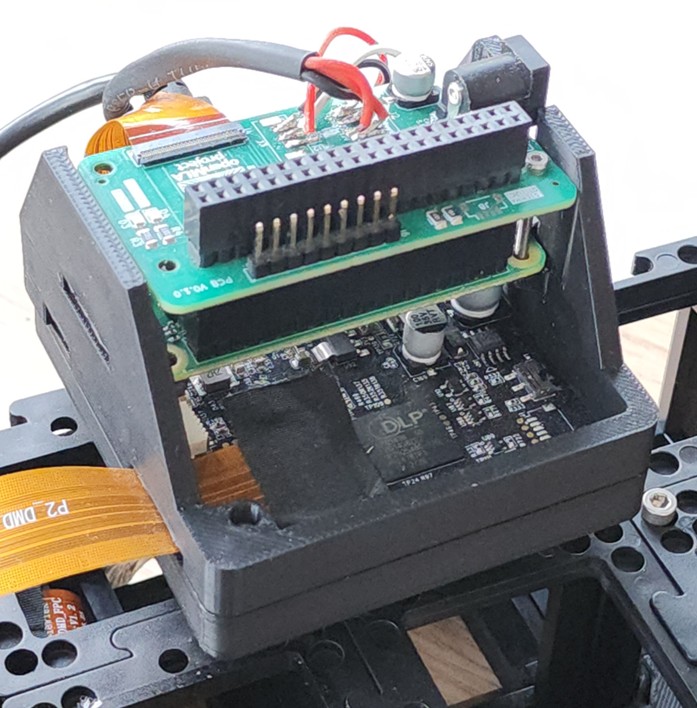
DMD Module
The DLP300S and controller are mounted inside a UC2 cube. The mirror tilt angle is approx. , requiring a specific beam angle for proper reflection.
Electronics
The Raspberry Pi Zero 2 controls the DMD via GPIO using a custom bridge board. It uses a standard 720p@60 video timing to drive the DMD.
Software
The system is controlled via ImSwitch. A custom plugin handles the communication with the Raspberry Pi (running a FastAPI server) to trigger patterns and acquire images.
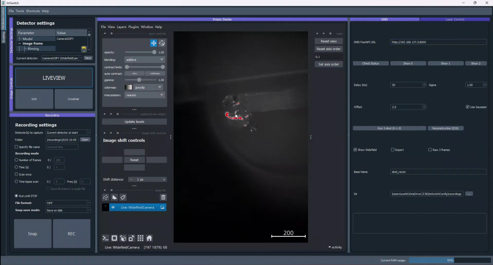
The software automatically handles:
- Pattern Generation: Creating the binary stripe patterns.
- Acquisition: Synchronizing the camera with the pattern display.
- Reconstruction: Running the RMS algorithm in real-time to produce the sectioned image.
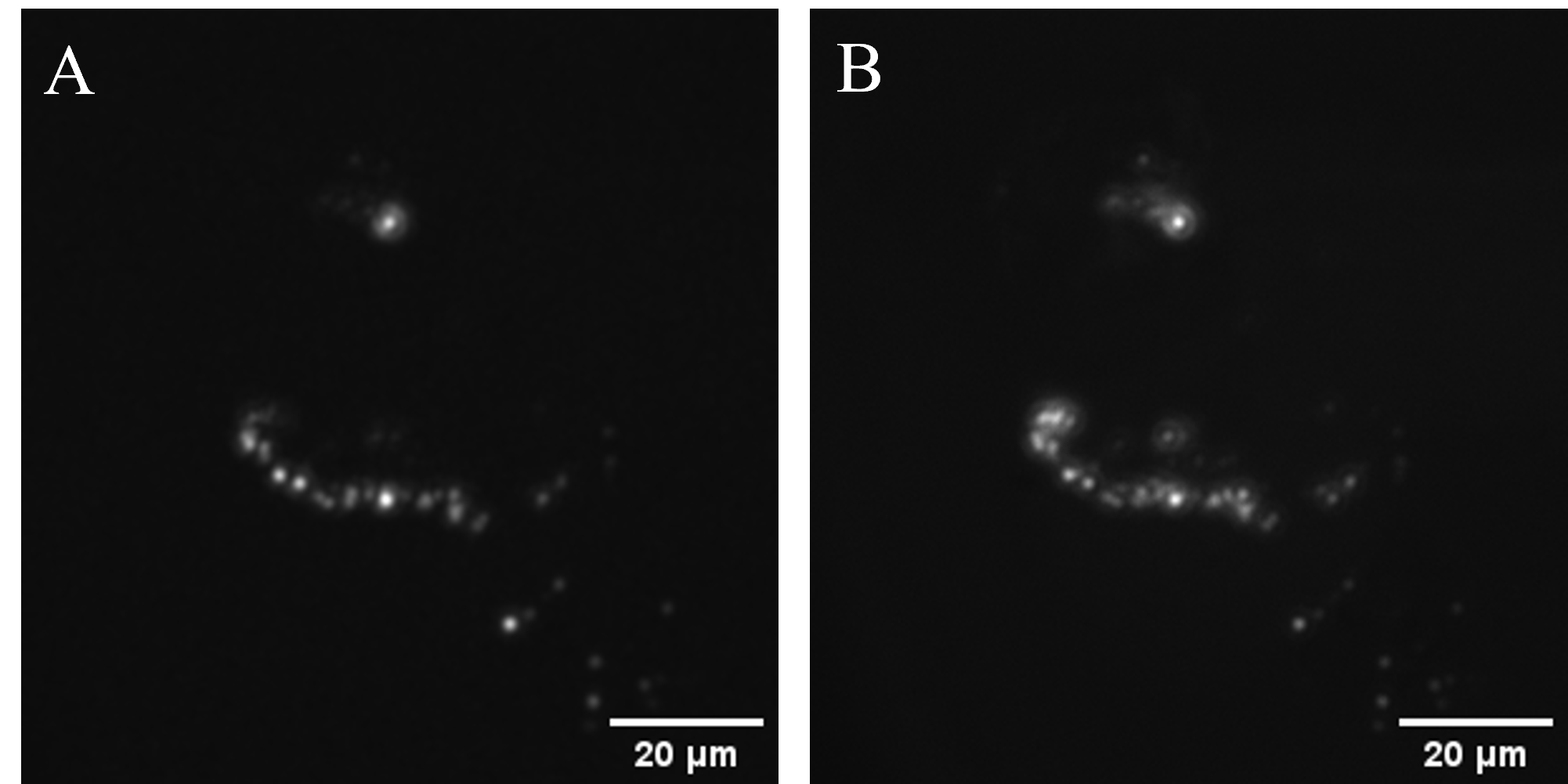
Preliminary Results
We tested the system on a fluorescent sample (fluorescent powder on a 3D-printed part).
Optical Sectioning Performance
Comparing the conventional wide-field image with the SIM reconstruction shows significant background rejection.
Zoomed View:
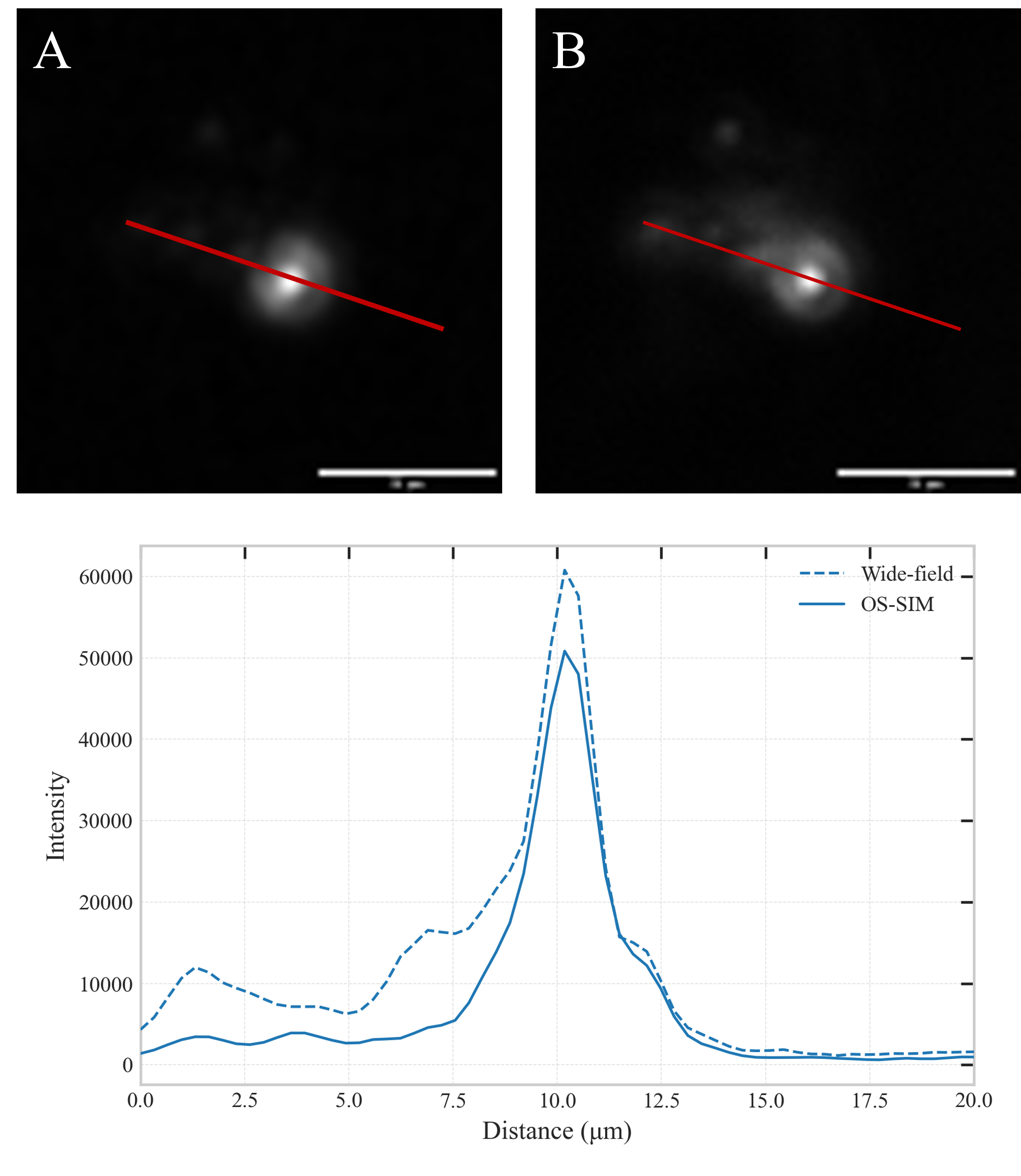
The SIM image (left/bottom) reveals fine surface details that are obscured by the out-of-focus haze in the wide-field image.
Last Updated: December 2025