Tutorial: Building a XXX
  Short introduction for Example:
  In this workshop, we will guide you through assembling a XXX
Image of complete setup
Materials Needed
- etc.
Diagram
image of black and white box diagram,
components labeled for easier understanding
Theory of Operation
Explanation of the finished setup for example:
Light-sheet microscopy is based on the principle of fluorescence and
like confocal microscopy, it is a technique that creates optical sections that can then be
reconstructed into a coherent image. It differs from traditional microscopy technologies in its special type of illumination and detection, which enables gentler and faster acquisition of 3D images, making it particularly suitable for the three-dimensional visualization of biological samples.
images as needed
Theoretical Background
Explanation of the physical prinziples the setup/ experiment is based on
for example: Fluorescence is a photophysical process that describes the spontaneous emission of light shortly after an electron is excited to a higher-energy state.
Tutorial: XXX
Image of all the components laying next to each other
needed for the setup/ experiment
Step 1: Assemble the XXX
Step by Step describtion on how to place the cubes and adjust the optical parts. No Electronics here!
This guide will walk you through the assembly step by step. You can follow the process according to the functional modules or refer to the diagram above for orientation.
placement
Image of finished 1. taskplacement
Image of finished 2. taskplacement
Image of finished 3. task
Step 2: Electronics
 *only if Laser is used*

  **⚠️ ATTENTION!**

  NEVER LOOK DIRECTLY INTO THE LASER! EYE WILL BE DAMAGED DIRECTLY

  NEVER SWITCH ON THE LASER WITHOUT INTENDED USE

  BEAM HAS TO GO AWAY FROM ONESELF - ALWAYS!
2.1: Plug in the Electronics as Shown Below
⚠️ Caution! If you need to change any of the cables or their position, always unplug the 12V power cable before doing so. Otherwise, the electronic components might get damaged!
⚠️
These instructions based on the Pinlay-Out of the ESO32-DEV-based UC2 standalone board V3 (beta)) find the Pin-layout for the ESO32-DEV-based UC2 standalone board V4 here
*image of complete Electronic setup (you can see every wire connected correctly)*
connect the LED-Matrix to the Mainboard at
LED1Connect the Z-stage to the position
Z-Motoron the main board. Ensure there's a motor driver.Connect the 3 Motors of the XYZ-Stage to the respective positions
A-Motor,X-Motor,Y-Motor. Ensure there are motor drivers as well.Connect the Laser to the Mainboard at
PMW1and to12VPower: (V3 beta board)Connect the Laser to the Mainboard at
XH-4-pin(V4 board. single color laser)Connect the Laser to the Mainboard at
XH-6-pin(V4 board. dual color laser)Connect the fluorescence LED to the Mainboard at
PMW2Plug in the micro-USB at your ESP32 and connect to your PC.
Plug in the 12V power cable.
*delete what is not needed*
2.2: Flashing the ESP32 Firmware
*is always the same , no changing here*
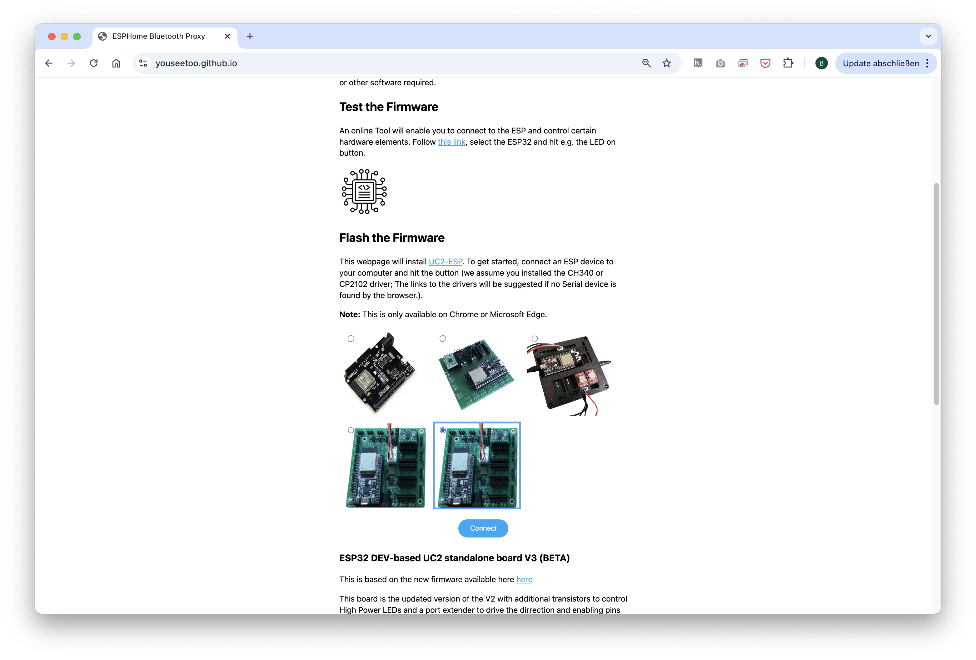
- Before proceeding, ensure your ESP32 board has the latest firmware. You can download and flash the firmware via the official openUC2 website, selecting your version, then click on the
connectbutton. The source code can be found here.
Flashing process shown for the ESP32-DEV-based UC2 standalone board V3 (beta).
- Connect the ESP32 to your computer using the micro-USB or USB-C cable.
In your Chrome browser, a dialog will prompt you to select the COM port for your ESP32, which should be shown as
CP2102 USB to UART Bridge Controller. Once connected, you can install the latest firmware by simply clicking the "Install" button.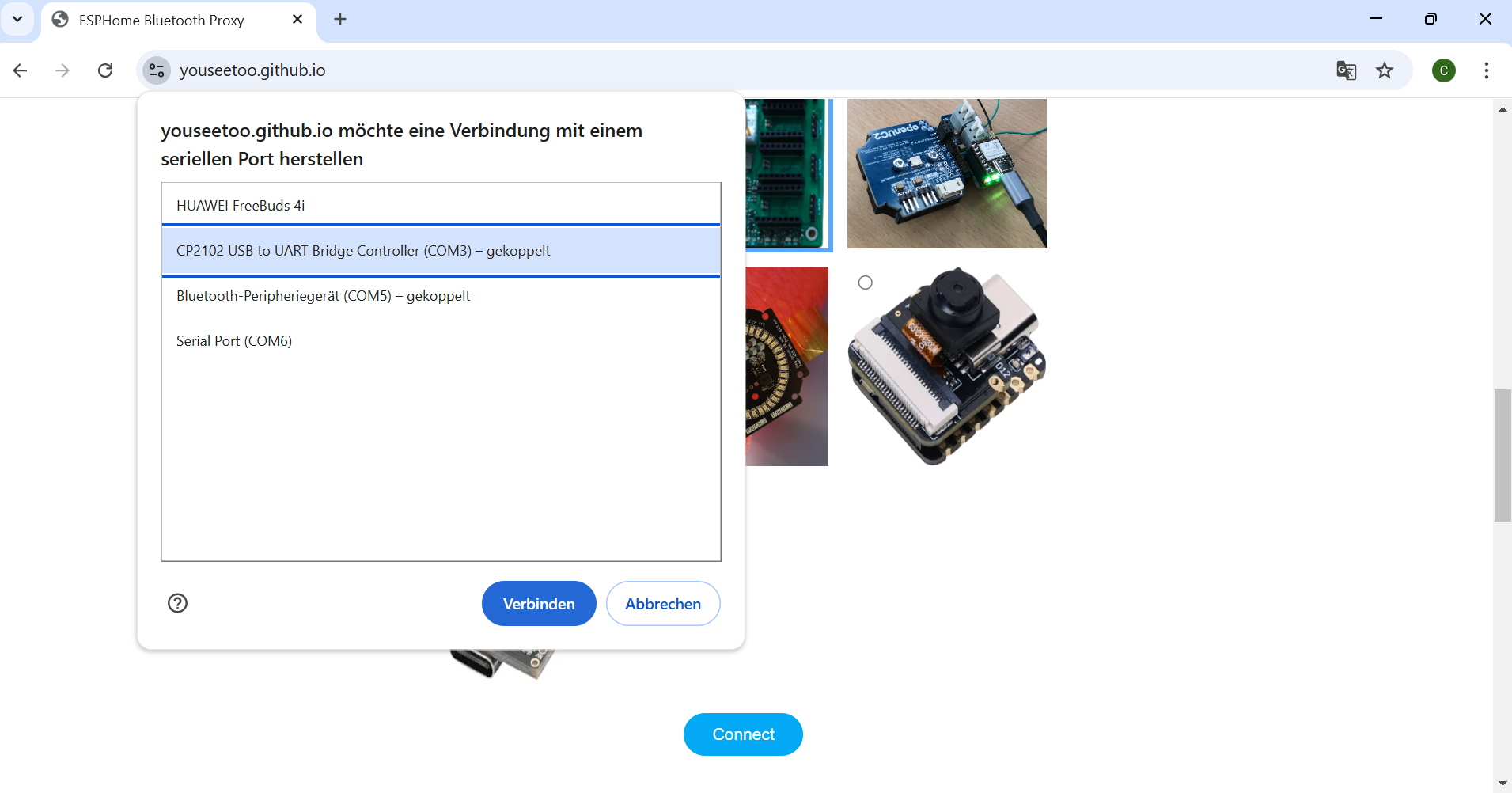

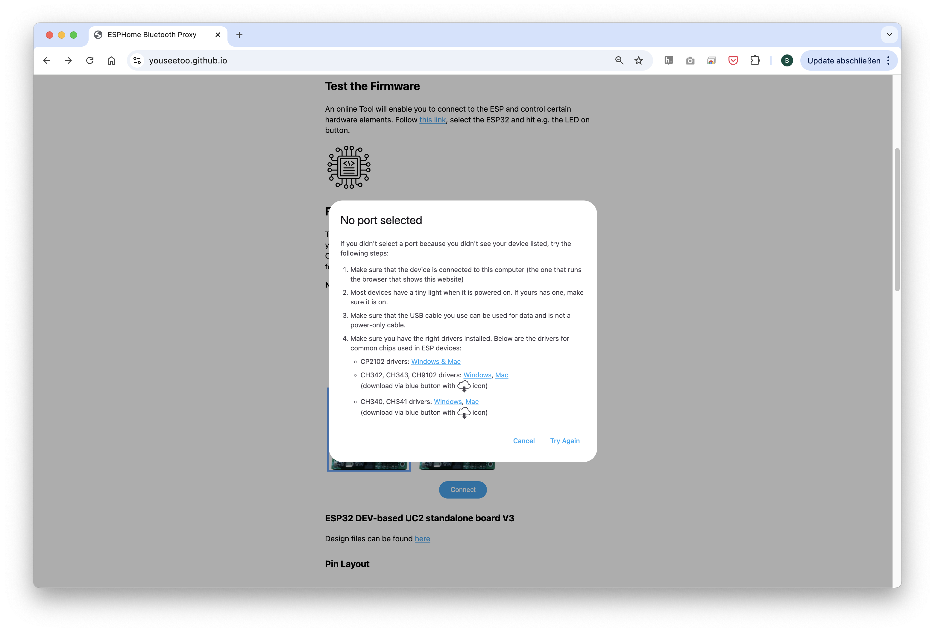
If nothing shows up, you can install the drivers from the prompt that appears when you click anywhere on the screen:
Wait until the firmware has been successfully flashed.
2.3: Connecting to the Web Interface
*is always the same , no changing here*
(valid since March 2025)
After flashing the firmware, go to the testing section on the same website.
Connect to your ESP32 board using the "Connect" button again, ensuring the correct COM port is selected.
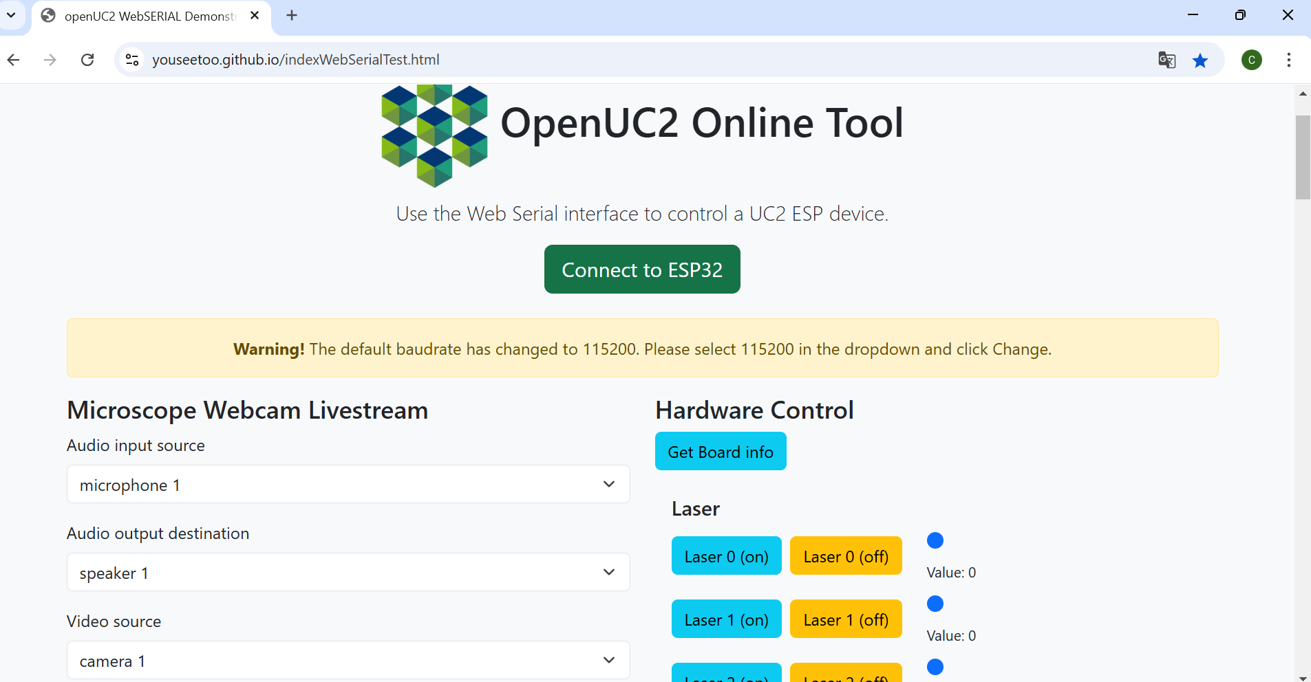
Once connected, test the system by sending a simple command:
{"task":"/motor_act", "motor": { "steppers": [ { "stepperid": 3, "position": -1000, "speed": 1000, "isabs": 0, "isaccel": 0} ] } }
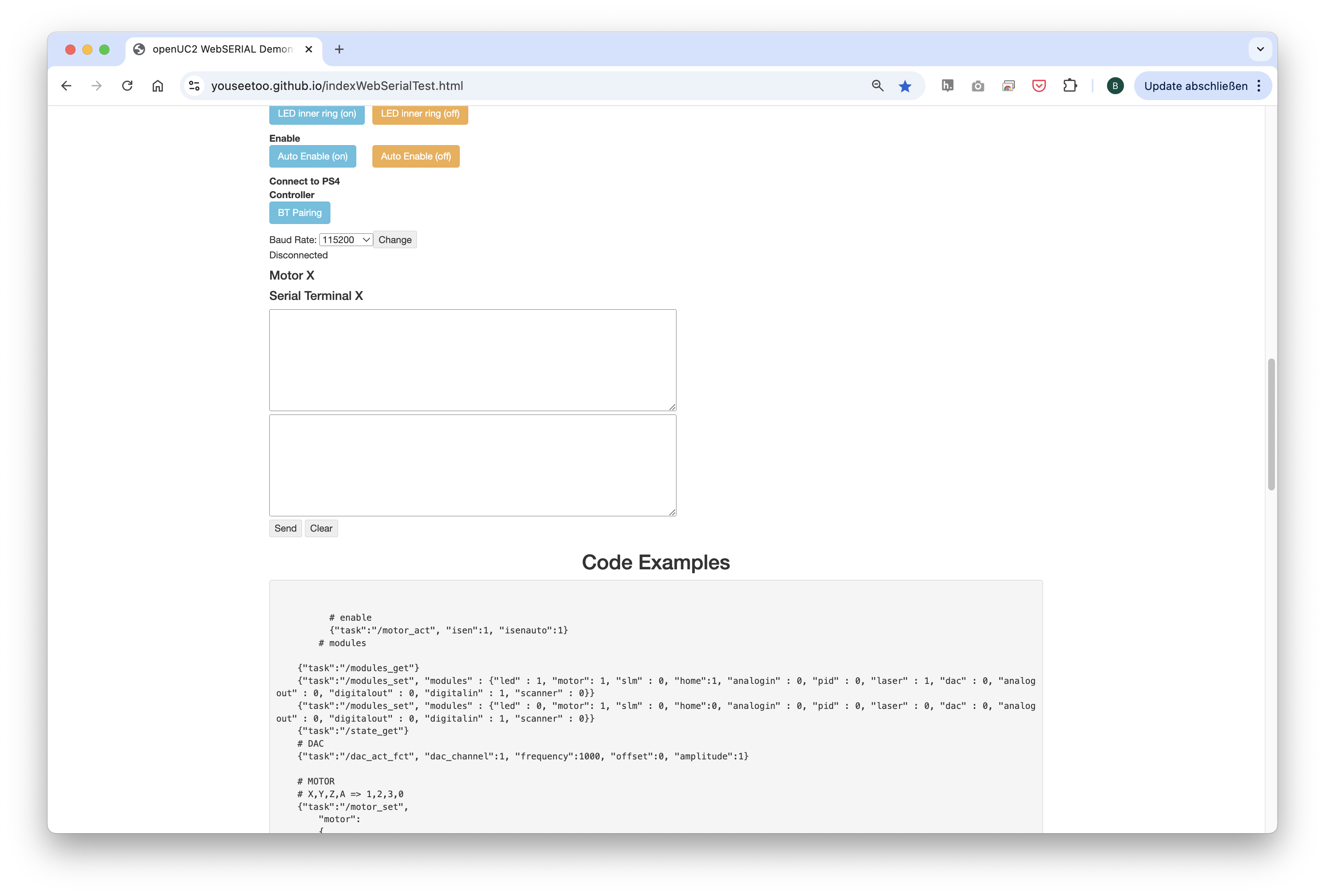
This command will move the Z-axis motor by -1000 steps (1 full rotation) at a speed of 1000 steps per second. Each step corresponds to a movement of 300nm when using microstepping. You’ll observe the motor rotating, adjusting the focus.
Note: Ensure that the command string has no line breaks.
2.4: Testing in the Web Interface
*is always the same , no changing here, just delete what you dont need*
(valid since March 2025)
After completing the test, go back to the first tab to control the other components via buttons:
PM1(on)andPMW1(off)control the laser.PM2(on)andPMW2(off)control the led.Motor Z(+)andMotor Z(-)control the Z-stage.Motor X(+)/Y(+)/A(+)andMotor X(-)/Y(-)/A(-)control the XYZ-stage.LED (on)andLED (off)control the LED-matrix panel, as well as the other buttons in this section to turn on single LEDs or a ring pattern.
2.5: Pairing the PS4 Controller 🎮
*only if some sort of motorized stage is used*
The UC2-ESP firmware supports various input devices, including the PS4 controller, to make interacting with the microscope easier. While you've already worked with USB serial commands, using the PS4 controller offers a more flexible, hands-on approach. For more detailed instructions on pairing, refer to theUC2 PS4 Controller Pairing Guide. Here’s a brief summary:
- Put your PS4 controller into pairing mode by holding down the
Sharebutton and thePSbutton simultaneously until the light bar starts blinking. - Click the
Pair Controllerbutton in the web interface. Alternatively, open the serial prompt in your browser (connected to the ESP32 board) or use the web interface and enter the following command:
{"bt_scan":1}
This will initiate the Bluetooth scan on the ESP32, which will detect and pair with the controller.
Once paired, you can control the motorized stage using the analog sticks and switch the LED-matrix on/off using the buttons. The complete pinout of the diffrent function you can find here: UC2 PS4 Controller Pairing Guide(valid since June 2025)
2.6: Setup and Use the Camera Software
*only if HIK Camera is used*
Instructions for the HIKROBOT - Camera - MV-CE060-10UM-PRO:
Connect the camera via cable to your PC.
For the installation process and useage of the software, follow these instructions: Install MVS App for Camera Utilization
Step 3: Aligning the XXX
Most of the Times Alliging the Experiemnt is only possible after the Electronic setup
task
Image of finished 1. tasktask
Image of finished 2. tasktask
Image of finished 3. task
Step 4: Install Imswitch (optional)
1. Installation process
For this, please refer to the installation instructions here.
On top of this, you can use the following ImSwitchClient template to remote control your microscopy using google colab or jupyter notebook. This gives some hints on the use of the API:
Your Setup is compete, now let's start the Experiments
Experiment 1:
step
Image of finished 1. stepstep
Image of finished 2. stepstep
Image of finished 3. step
Experiment 2:
step
Image of finished 1. stepstep
Image of finished 2. stepstep
Image of finished 3. step