Combine Calliope with the Michelson Interferometer
Flyer: Experiment for Schools
In an Interferometer, a laser-beam is divided, travels separate paths, and is then mixed together again. This results in a ring-pattern on a screen, because constructive and destructive interference happens at the different points.
In science and and technology, interferometers are often used as sensors, because every tiny change of the light-paths results in a big change in the interference pattern. In this way, turbulences in air become visible or tiny structures on a surface can be measured.
By heating on of the mirror elements and the resulting expansion of the material, one of the paths shrinks a very small amount. But a change in path length of only 325 nanometers results in an inversion of the interference pattern, which makes it observable by eye and in real-time!
The Michelson-Interferometer is part of the high school physics curriculum nationwide. Our rugged construction and assembly through "plugging together" also enables practical lessons and labs much earlier. With the Calliope Mini 3, students can program the heating and collect measurements from the experiment, to then i.e. prove physical correlations in their lab report.
- Assembling the interferometer reinforces the knowledge about the anatomy of the Michelson-Interferometer (task level 1).
- Adjusting the mirrors promotes intuition and requires understanding the functions provided by the the optic components in the assembly (task level 2).
- To design an experiment-method, to program, to collect data and deduce correlations from it is real scientific practice (task level 3)!
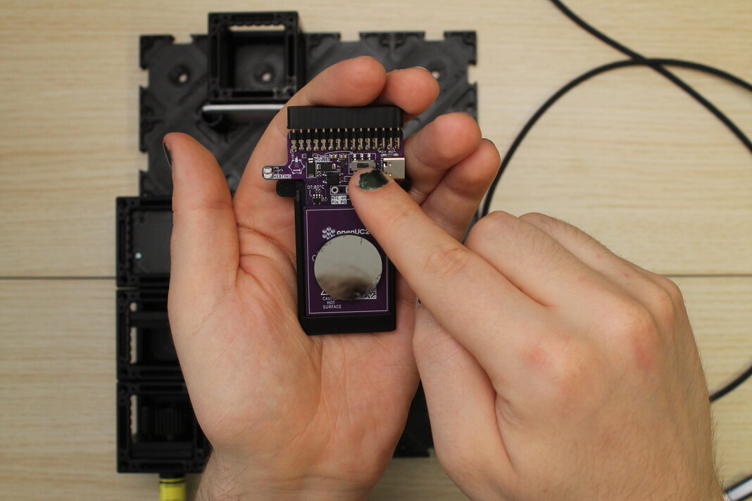
Anatomy of the heated mirror assembly
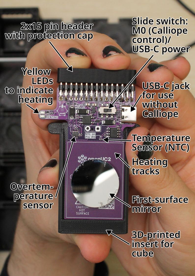
Slide switch: M0 (Calliope control)/USB-C power
If the plastic lever of the switch is in the left position, the heater can be controlled via Calliope Mini 3's "M0" output. With the lever to the right, the heater is directly connected to the power of the USB-C jack.
USB-C jack for use without Calliope
When a power source is connected here, the heater is heating if the slide switch is set to the right "USB" position. It will heat and only stop heating if the power is removed, the slide switch is toggled, or if there is overtemperature (Over 80°C).
Temperature Sensor (NTC)
The temperature sensor is a resistor with a negative thermal coefficient, so the resistance decreases as temperature increases. The part name is NCP15WF104F03RC by muRata.
"B constant 25-80°C" is 4303K. The datasheet has a lookup table (Search for "NCP15WF104D").
127.1k@20°C,100k@25°C,50.7k@40°C,22.2k@60°C,10.5k@80°C.
The NTC is on the high side of a voltage divider to 3.3V, with the middle to the positive input of a LM358 op-amp as buffer, and on the low side 49.9k Ohms to GND.
Best would be to "calibrate" the Calliope ADC values to known temperature references, or to accept arbitrary units.
Heating tracks
The heating track is a single long copper track of the printed circuit board that continues on the back side of the circuit board. The meandering track is 0.2 mm wide, in total 5916 mm long, and printed on 1 oz/sqft circuit board. Its resistance (calculated) should be 14.4 Ohms at 25°C and 17.4 Ohms at 80°C.
With Calliope M0 at 100%, or USB, there should be 4.6V across the heater.
First-surface mirror
The circular mirror reflects on its first, exposed front surface and has a diameter of 24 mm.
It is fixed to the heating area of the circuit board with a pad of double-sided tape.
3D-printed insert for cube
The circuit board is fixed into the 3D-printed part with tape. The side edges of the 3D-print allow it to slide into the top and bottom notches of the UC2 cubes to fix it securely into the cube. With another 3D-printed part, the assembly can be inserted into a cube in a 45° angle.
Overtemperature sensor
This sensor will interrupt the heating if the sensor is above 80°C. It will turn it back on if its temperature falls below 78°C. It will interrupt heating on both modes, Calliope M0 or USB. When heating is interrupted, the yellow LEDs are also off.
Yellow LEDs to indicate heating
Whenever the heating track is powered, one of the yellow LEDs will be lit. On USB-C power or when Calliope M0 is set to a positive value, the top LED will light. If Calliope M0 is set to a negative value, the bottom LED will light.
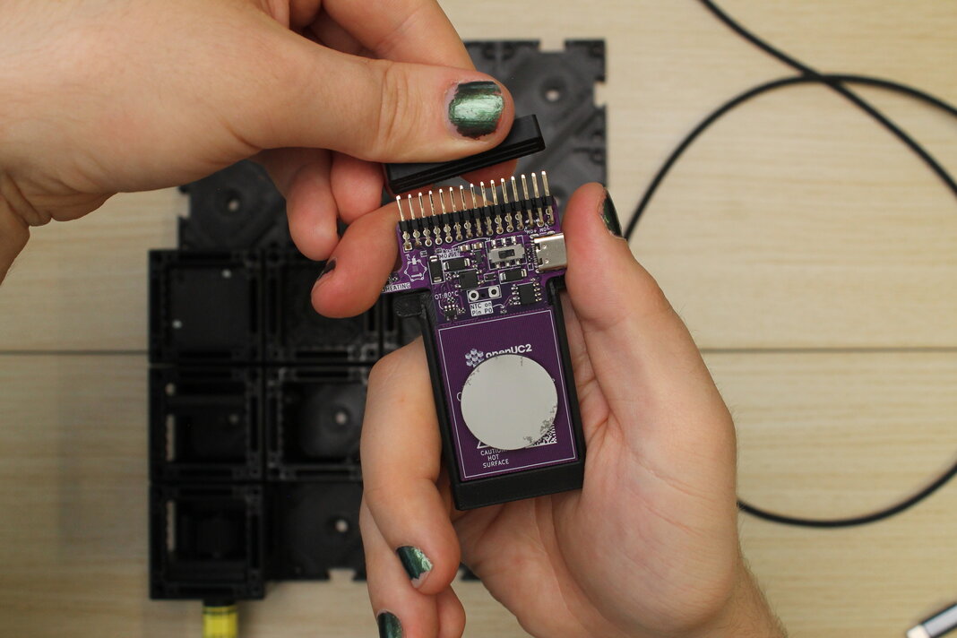
2x15 pin header with protection cap
This header can be plugged into the bottom of a Calliope Mini 3, with the calliope's USB port facing away from the mirror.
This connects to the following Calliope pins:
| Function | Calliope pin |
|---|---|
| Heating | M0 |
| Temperature sensor | P0 (analog) |
Step-by-step Tutorial
What you will need

Also, something like a laptop that can program the Calliope.
1. Center the laser on the screen
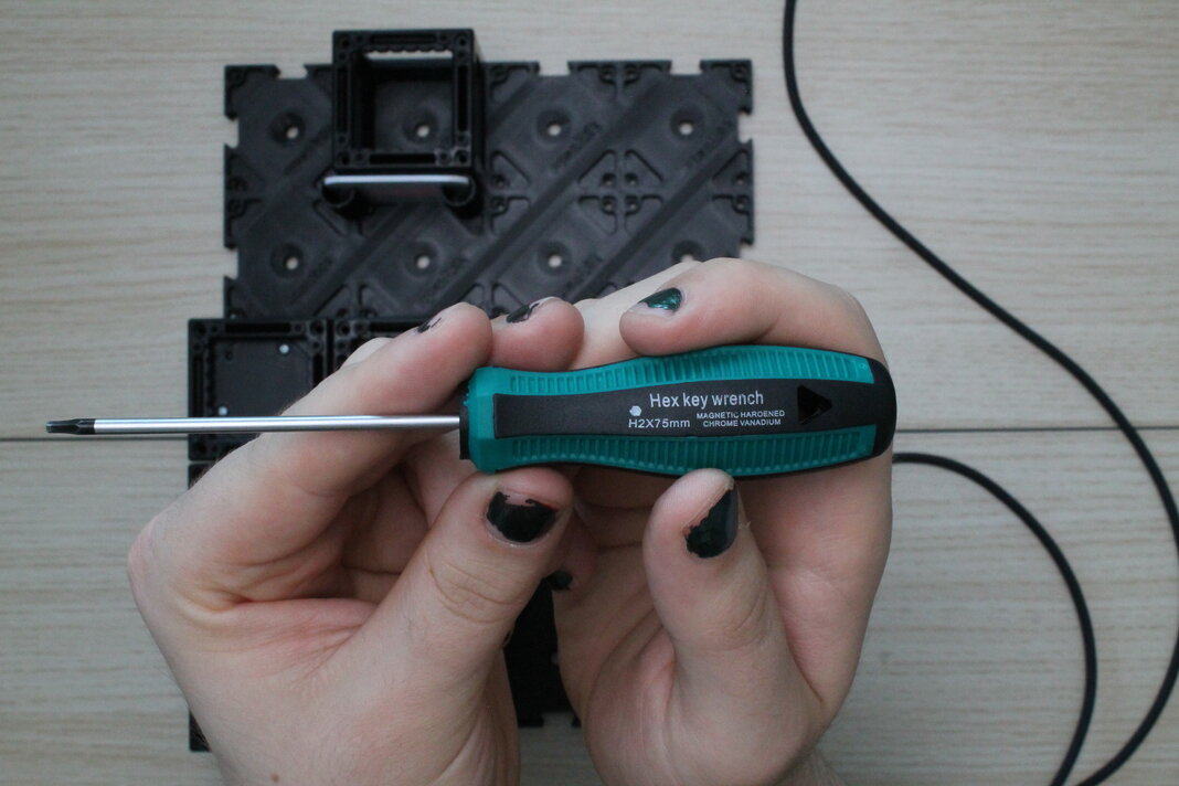
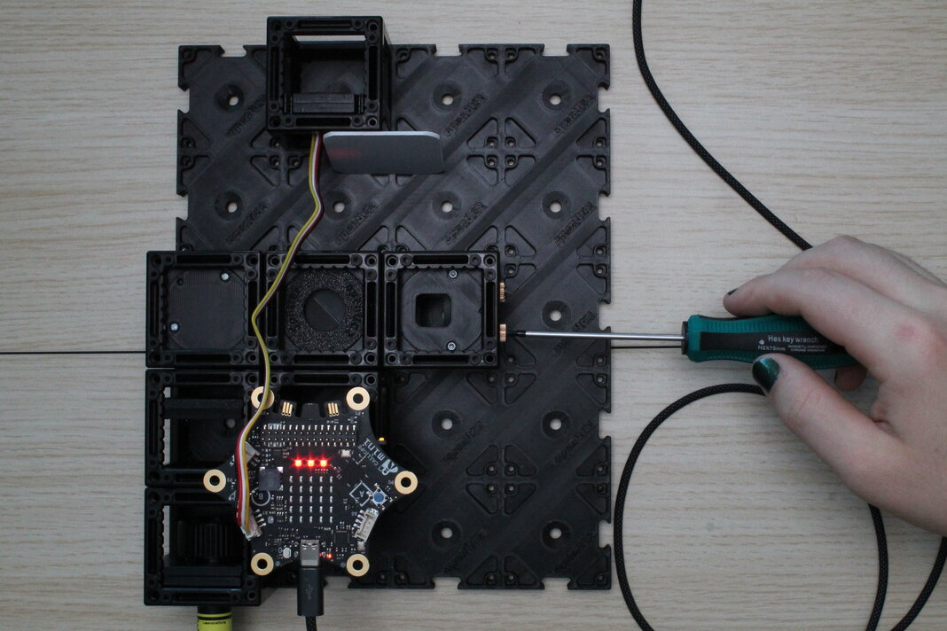
Build a Michelson interferometer with a screen, and turn on the laser. Now, look for the screwdriver that fits into the set-screws of the kinematic mirror mounts. It should have Hex drive with size H2.
Adjust the 45° kinematic mirror so that the laser-beam is in the center on the screen. This can be done with just the one kinematic mirror in the experiment.
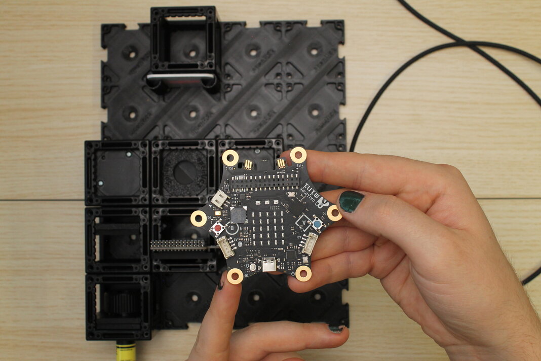
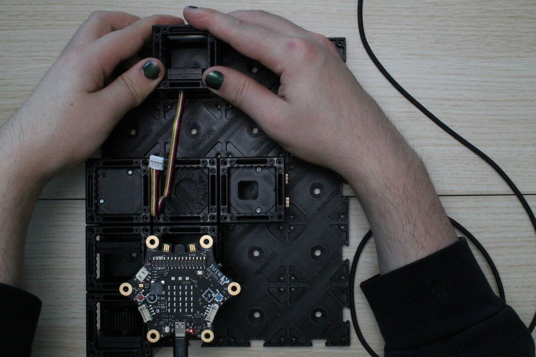
2. Set the heater to "M0" mode and plug the Calliope onto it
On the purple circuit board, slide the switch to the left to put it in the "M0" position. The plastic lever should be on the left side.
Remove the protection cap from the 2x15 pin header. Pull straight up and be careful not to bend the pins.
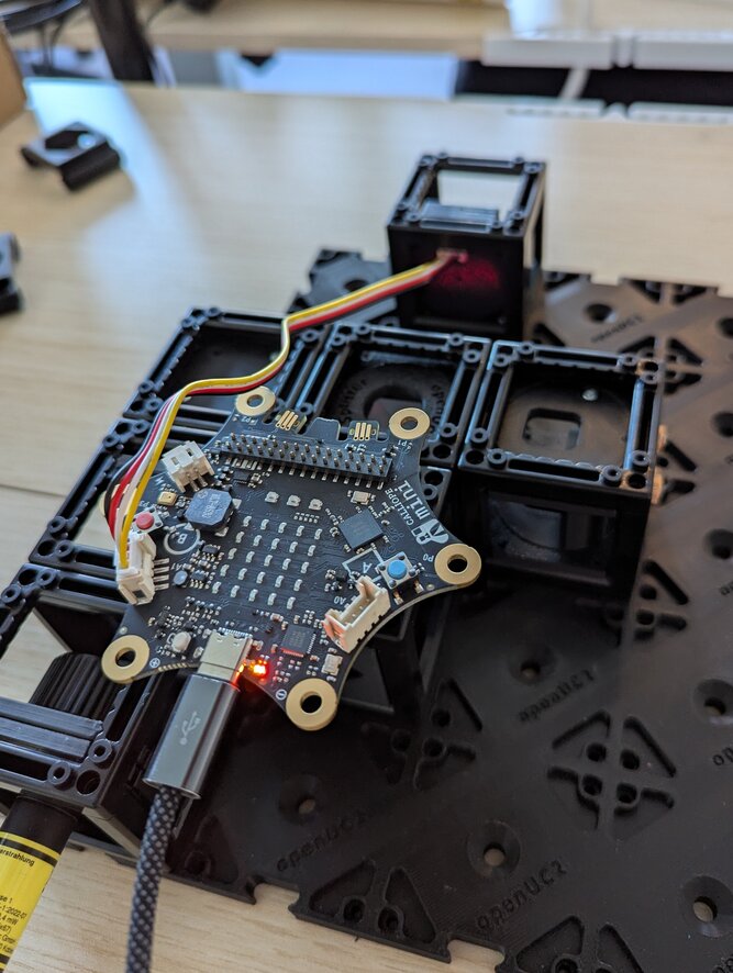
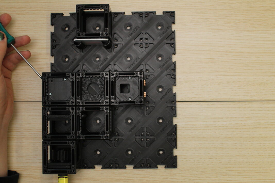
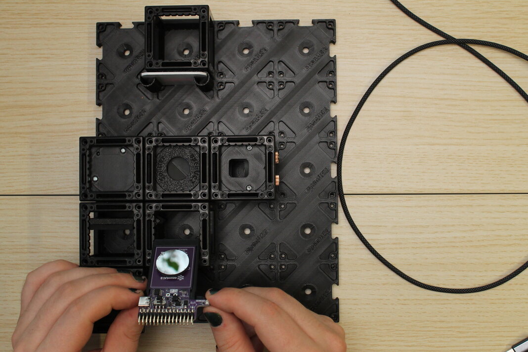
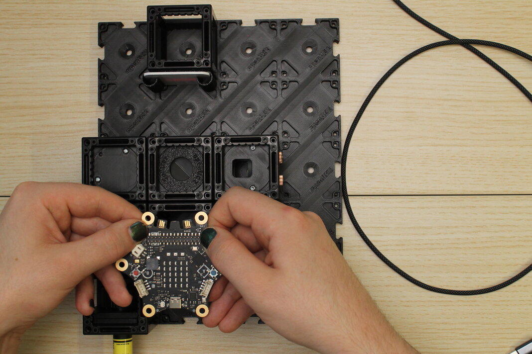
Put the heated mirror assembly into the experiment, in the 5th notch and with the mirror facing the screen. The surface of the mirror should now be perfectly in the center of the cube.
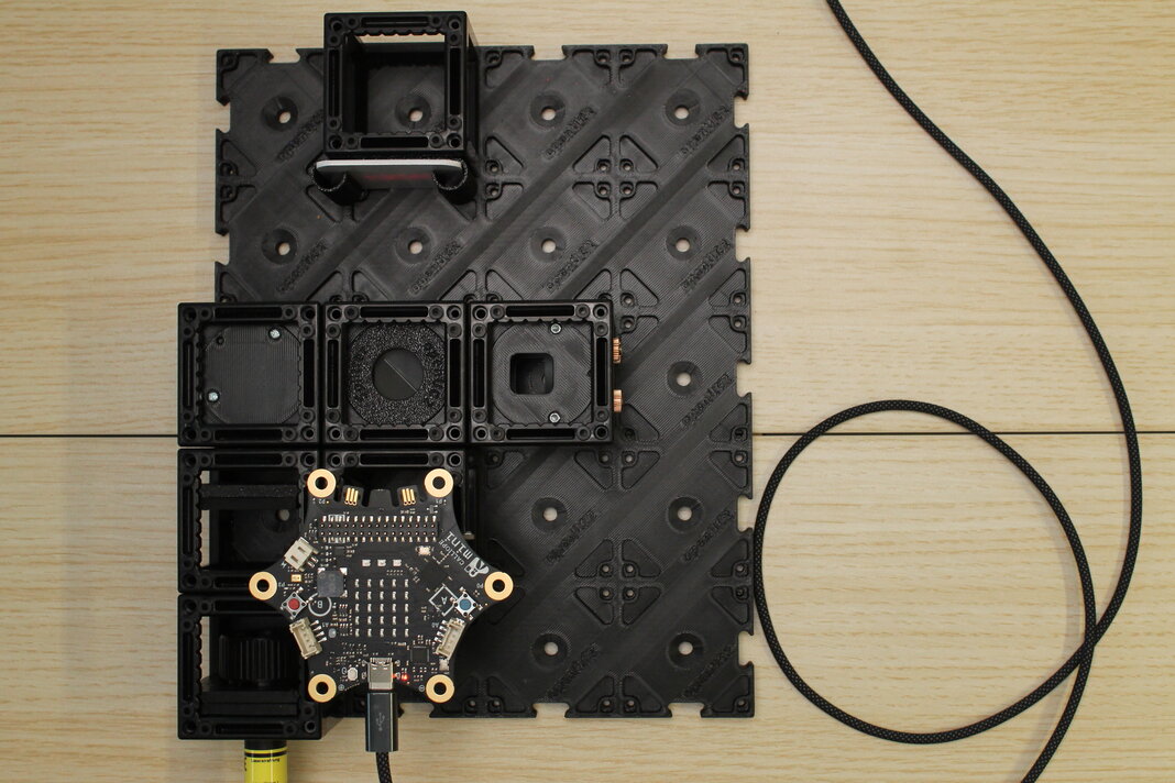
Now, carefully push the Calliope Mini V3 onto the pin header. The Calliope's USB-C port should face away from the screen. Try to push the pins into the header on both sides so that the pins don't bend.
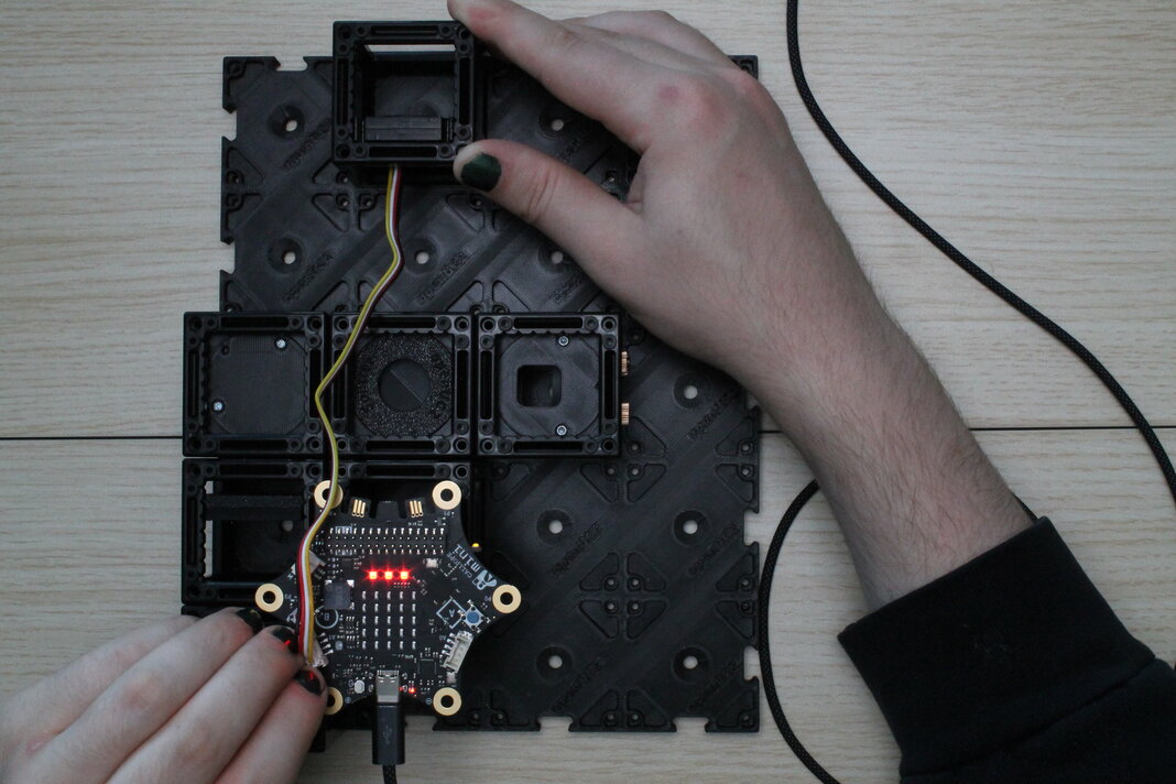
3. Plug the Calliope into USB-C and adjust the mirror to get an interference pattern
Plug a USB-C cable into the Calliope, and into the laptop to program it. Layout the cable so that it is not in the way, and so that it won't get caught on anything. If the laptop is running and outputs USB power, a red LED on the Calliope should be lit, close to the USB port.
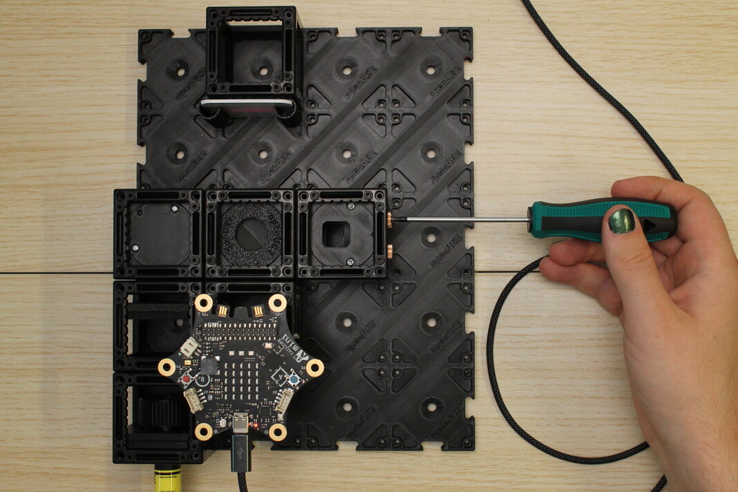
Now, adjust the kinematic mirror in the other interferometer leg until you can see an interference pattern on the screen. Use a screwdriver in the 3 leadscrews to change the angle up/down, left/right and diagonally.
Hint: The Laserbeam (including dust on the expander lens and the 45°-mirror) is being "copied" by the beam splitter, and should eventually be joined again where both copies align perfectly. Try to align the dust particles that you can see on the screen! If they are aligned, you should start seeing the ring pattern, or a stripe pattern (the edge of the ring pattern).
Try to bring the central ring fully onto the screen. Around it will be the widest regions of amplification and elimination, which will make it easier to see.
4. Program the Calliope to heat the mirror
First, we want to observe with our eyes what happens when the one mirror of the interferometer is heated.
On the laptop with a Chromium-based browser (Edge or Chrome), go to makecode.calliope.cc and start a new project. Give the project a name and select v3 (because it is the Calliope Mini 3).
To heat the mirror, use the block from the "Motors" menu. The purple PCB has its heater track connected to the "M0" pins of the Calliope, so you can leave the default motor number selected.
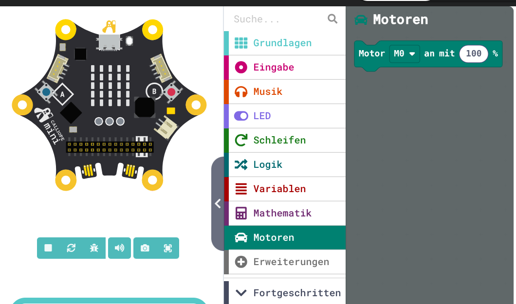
When the motors are run, power will flow through the long conductive track on the circuit board and it will heat up slowly. Because electrically this is just a resistor, it will heat the same whether the motor is set to 100% or -100%.
While it is heating, you will see one of the yellow LEDs are lit. Setting M0 to + direction will light the top LED, and - direction will light the bottom yellow LED.
If everything is adjusted correctly, you should see the pattern "growing" when the mirror heats up, and "shrinking" when it cools down. The inside of the center ring just changes from dark to bright.
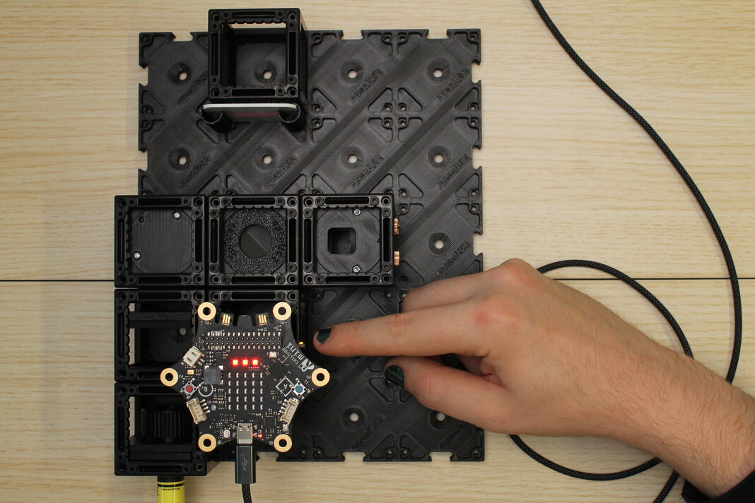
*Interference pattern appears "growing" when heating the mirror, and "shrinking" when it cools.*5. Add a light sensor instead of the screen
With our setup so far, we can control the heating through programming, but we have to observe the pattern with our eyes (or a phone camera). To observe it more scientifically, we should add a light sensor and let the Calliope measure light intensity at a small point in the interference pattern.
The Grove Light Sensor by Seeed Studio should be in a 3D-printed round part, in between two "master insert" plates. You also need a Grove cable of at least 20 cm length. The cable that comes with the light sensor works.
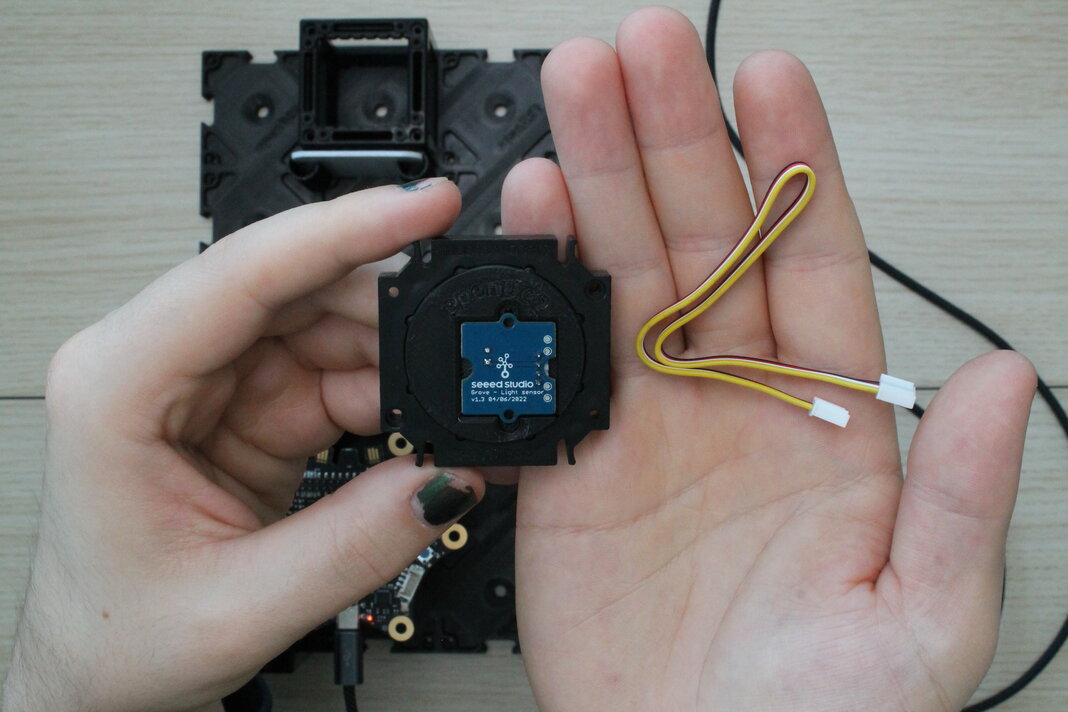
On the side with the pinhole aperture and the Grove connector, plug one end of the cable into the connector.
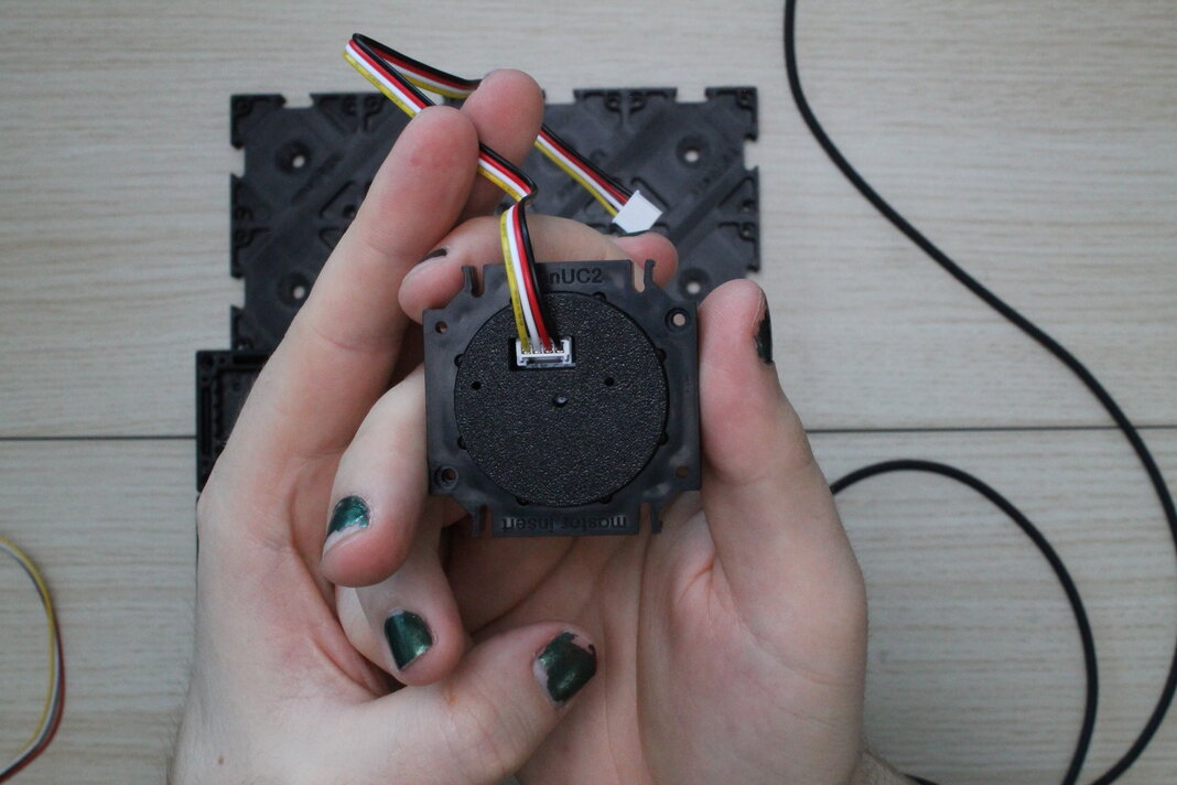
To insert this into a cube, you may have to disassemble the cube that is holding the screen. The sensor cable should come out above the pinhole once it is in the experiment, so stand the light sensor assembly into one half-cube, with the cable on the opposite side of the studs.
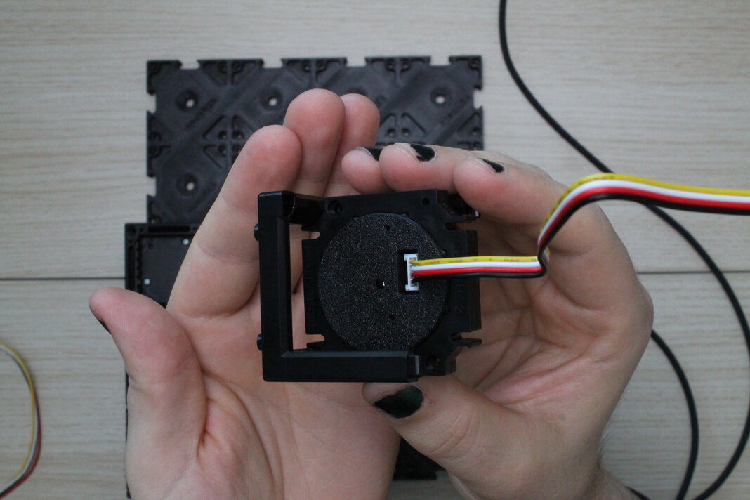
Close the cube with another half-cube. Make sure the insert sits squarely inside the cube, and that the cube-halves are fully closed.

Push the sensor cube into the baseplate where the screen used to be.
6. Connect with Calliope and re-adjust to get the interference pattern
Plug the other end of the Grove cable into the "A1" jack on the top side of the Calliope. This will be a little tight but should work if the cable comes out above the pinhole on the sensor side.
Lean the white screen against the cube with the light sensor to see the laserbeam again, and adjust the kinematic mirror in the other leg of the interferometer to get the interference pattern back. The angle of the heated mirror has changed from before, because now the sensor cable is pulling on it.
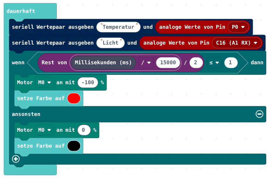
7. Program the calliope to measure the heater's temperature and the light intensity, and send it via Serial
In Makecode, program the Calliope to periodically turn on and off the heat.
The whole time, measure temperature (analog) and light intensity (analog). Send the data to the computer via Serial. Send name and value in one line, so that the computer can sort the received data.
| Function | Calliope pin |
|---|---|
| Heating | M0 |
| Temperature sensor | P0 (analog) |
| Grove Light Sensor | C16 (A1 RX) |
Below the Calliope graphic, open the received data monitor. It should automatically draw 2 nice graphs, and even autoscale the value range.
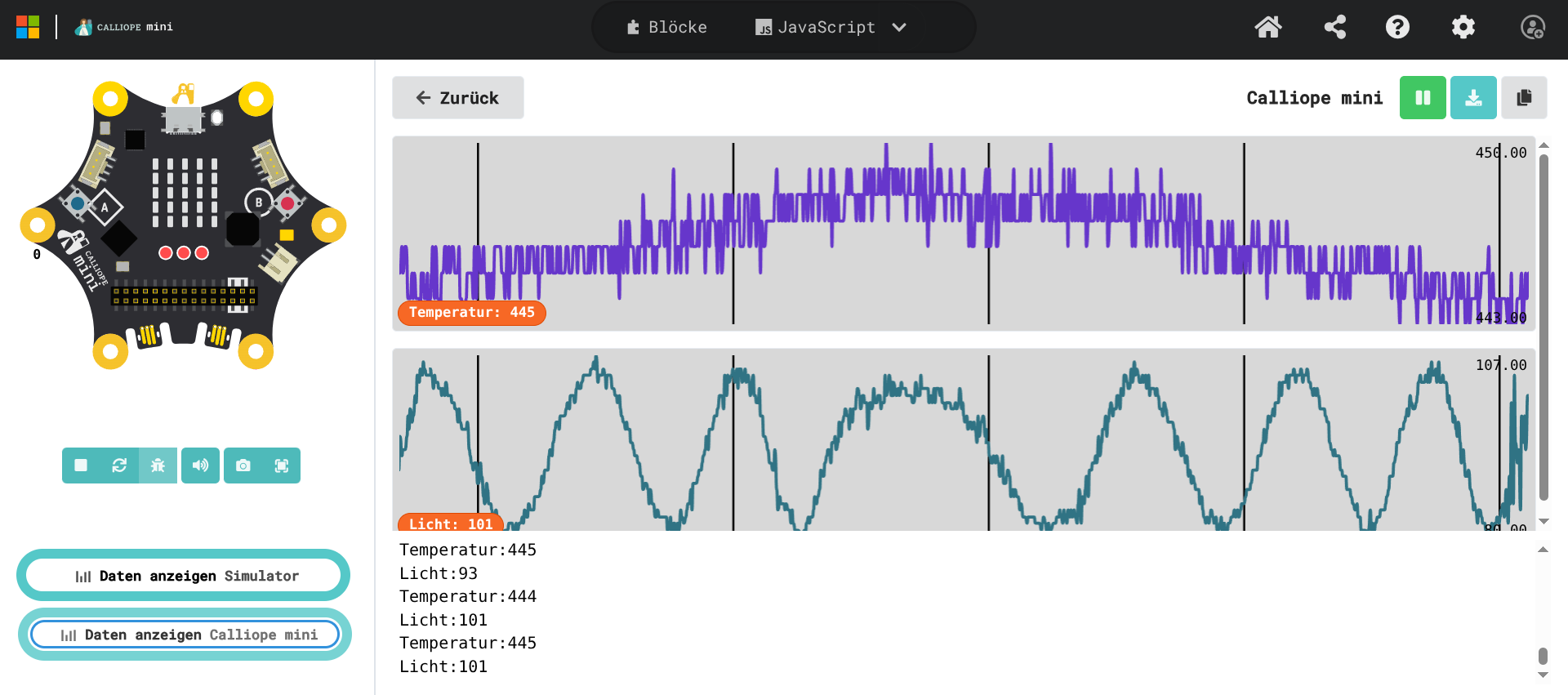
The received analog values are what voltage the Calliope sees at its pins. It divides the range between 0V and 3.3V linearly into 1024 parts. However, the parts like the light sensor (photodiode) or the NTC don't work linearly. The easiest way to calibrate the physical properties to the measured values would be to use known references, expose the sensors to them, and note the measured value. However, the relative change in the two measured values is good enough.