Crossed Polarizers

Crossed Polarizers are used to analyze the polarization of light. We use two linear polarizers, which are located perpendicular to each other. [1]
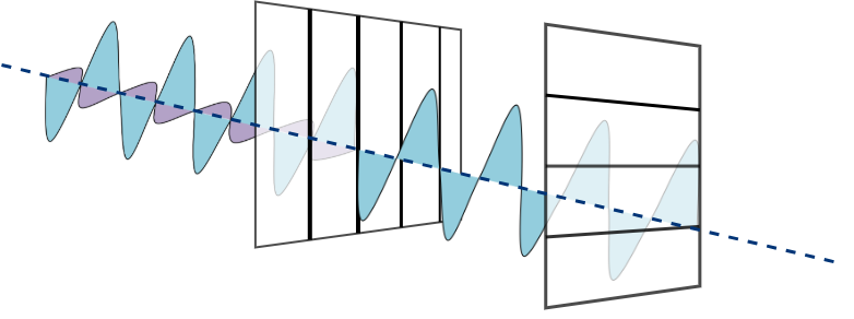
In the experiment, the polarizing direction of the first polarizer is oriented vertically to the incoming beam, and it will allow passing only vertical electric field vectors. After the first polarizer, we have an s-polarized light wave. [2]
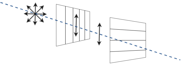
The second polarizer is located horizontally to the electric field vector. It blocks the wave which passes through the first polarizer. These two polarizers should be oriented at the right angle with respect to each other. You can see the orientation of the linear filters and light polarization change during the experiment in the figure below.
Time to build a Crossed Polarizers setup!
 Parts
Parts
Modules for this setup
| Name | Properties | Price | Link | # |
|---|---|---|---|---|
| 4×1 Baseplate | Skeleton of the System | 5.47 € | Base-plate | 1 |
| MODULE: Polarizer Cube | It holds the linearly polarizing filter | 8.62 € | Linear Polarizer | 2 |
| EXTRA MODULE: Sample Holder Cube | It holds the Sample (Not Used in Practice) | 1.3 € | Sample Holder | 1 |
| EXTRA MODULE: Screen Holder Cube | It holds the Display Screen (Not Used in Practice) | 1 € | Screen | 1 |
| EXTRA MODULE: Flashlight Lamp Cube | Light Source | 7.2 € | Flashlight | 1 |
 Parts to print
- 1 × Base-plate 4×1
- 2 × Cube base 1×1
- 2 x Cube lid 1×1
- 2 × Polarizer Guide
- 2 × Polarizer Wheel
- 2 × Polarizer Lid
Extra Holder Parts but NOT USED in our experiment: - 1 × Sample Holder
- 1 x Sample Holder Clamp
- 1 x Sample Holder - comb
- 1 × Flashlight Holder
 Additional components
- Check out the RESOURCES for more information!
- 1 × Linear Polarizing Sheet 🢂
- 16 × 5 mm Ball magnets 🢂
- 16 x Screws DIN912 ISO 4762 - M3×12 mm 🢂
- 6 x Screws DIN912 ISO 4762 M2×16 mm 🢂
- NOT USED 1 × flashlight 🢂
 Assembly
- Baseplate
- Linear Polarizer Cube
EXTRA MODULES: - Sample Holder Cube
- Sample Holder for Screen
- Flashlight cube
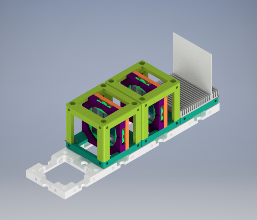
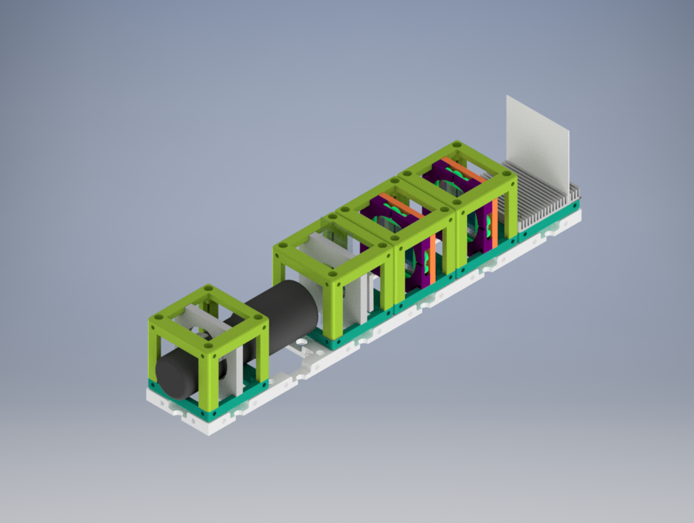
If all written modules are used in the experiment, the setup will look like:
 Results
We printed and assembled two Linear Polarizer module parts. Then, we bought the necessary components and inserted them into cubes.
You will find the basic version of Crossed Polarization experiment without a specific sample and additional light source below. We demonstrated the experiment with a room light.
We can observe the direct effect of the angle between two linear polarizers in the video below. The intensity of passing light through crossed polarizers changes when the direction angle of the polarization filter changes 360 degrees.
New Ideas
We are open to new ideas. Please contribute to the project freely, this place is a free country which is built by codes and machines :robot:
References
[1] Introduction to Polarized Light. (n.d.). Nikon’s MicroscopyU. Retrieved February 15, 2021, from https://www.microscopyu.com/techniques/polarized-light/introduction-to-polarized-light
[2] Logiurato, F. (2018). Teaching Light Polarization by Putting Art and Physics Together. The Physics Teachers, 1–5. https://arxiv.org/ftp/arxiv/papers/1803/1803.09645.pdf